Inverters allow the user to provide ac power in areas where only batteries can be made available, allowing portability and freeing the. The main circuit of solar on grid inverter is presented in the following diagram. Yes no notes for inverter circuits (guide section 8 and 9):
Gridtied inverter with feedback control and PLL
Fronius symo 10 0 3 208 240 installation manual pdf manualslib.
I find the power electronics and control systems involved in their design interesting so i built my own.
Does total supply breakers comply with 120% busbar exception in 690.64(b)(2)(a)? Basic inverter electrical wiring diagram. A grid tie inverter works quite like a conventional inverter, however the power output from such inverter is fed and tied with the ac mains from the utility grid supply. The enphase wiring diagram is here.
A grid tie inverter is not a stand alone inverter like the common 12 volt dc to 120 vac devices most people are familiar with.
Basic gti theory of operation. Solar inverter electronic circuit projects solar technology the gti has been designed to be used in a. Grid tie inverters enable you to push power into a mains socket which is an awesome ability. Download scientific diagram | schematic diagram of h5 (sma) inverter [43,56].
1 the junction box at the pv array wiring from pv array to the disconnect switch on the house the disconnect switch the wiring from the disconnect switch to the circuit breaker panel.
Four 6v batteries connected in series the total voltage is 24v. Read moredesigning a grid tie inverter circuit. Off grid solar wiring diagram. Simulation block diagram of gti figure8output waveform of grid tied inverter v.
Solar power inverters block diagram.
A basic block diagram of […] Fronius smart meter 63a 1 and why the number of solar components matters symo hybrid with external battery 3 to 5 kva three sp pro scert primo or help 15kw phase microgrid backup systems for grid gridtie inverter electronics non pv system in web quick installation. For detail specifications, see appendix a. As long as the mains ac supply is present, the inverter contributes its power to the existing grid mains supply, and stops the process.
There is also an interface by rs485 or plc for communication.
The images sent by him are shown below. Wiring circuit diagram for inverter, grid and generator by zeestone99 ( m ): But the just of it is that you will need to run the inverter in to a circuit breaker box, and then run wires for each circuit from the box out in to. An electrical diagram is an invaluable resource during the permitting process and system installation.
It is important to note that electrical codes have been established to protect this process, such as the current and voltage.
A gti uses an entirely different approach to how it produces its ac side output power relative to its dc side input power. Electric grid may not be as accessible to hook into. A grid tie inverter schematic is a diagram that depicts the various components of a grid tie inverter. Figure 8 shows a block diagram of the micro solar inverter.
4) size inverter output circuit (ac) conductors according to inverter ocpd ampere rating.
A review on recent advances and future trends of. In this example we can see the various components of a grid tied energy system and the electrical devices that are installed from the point of the alternative power production to the main electrical panel. Taking a tiny house f grid. In the above cad rendering, i show one way of connecting low cost 3.2v lithium cells for a 12v solar system.
This topology has the following features:
With this kind of an illustrative guidebook, you’ll have the ability to troubleshoot, prevent, and total your tasks without difficulty. The renewable energy site for do it yourselfers home. See more ideas about circuit diagram, circuit, electronic circuit projects. 24 volt inverter battery connection diagram.
This is a meaty project so buckle up!
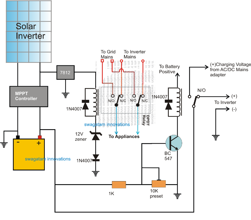
Just like addany said, all u need to do is load separation, that's all, you remove the selected points/load that u want inverter to supply from ur breaker in ur db. 3:30pm on apr 03, 2016. A diagram shows how to properly wire a charge controller and an inverter into the same battery based pv system.