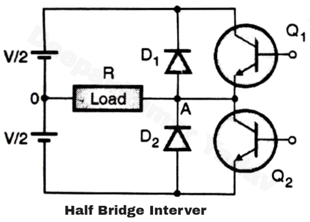
It is easier to obtain a regulated voltage than a regulated current, and voltage source type inverters can directly adjust the voltage applied to a load by The vsi type inverter has a dc voltage source with less impedance at the input terminals of an inverter. Current source inverter (csi) − a current source inverter is supplied with a variable current from a dc source that has high impedance.
(a) three phase voltage source inverter (b) PWM voltage
In vsi, the input is a voltage source.
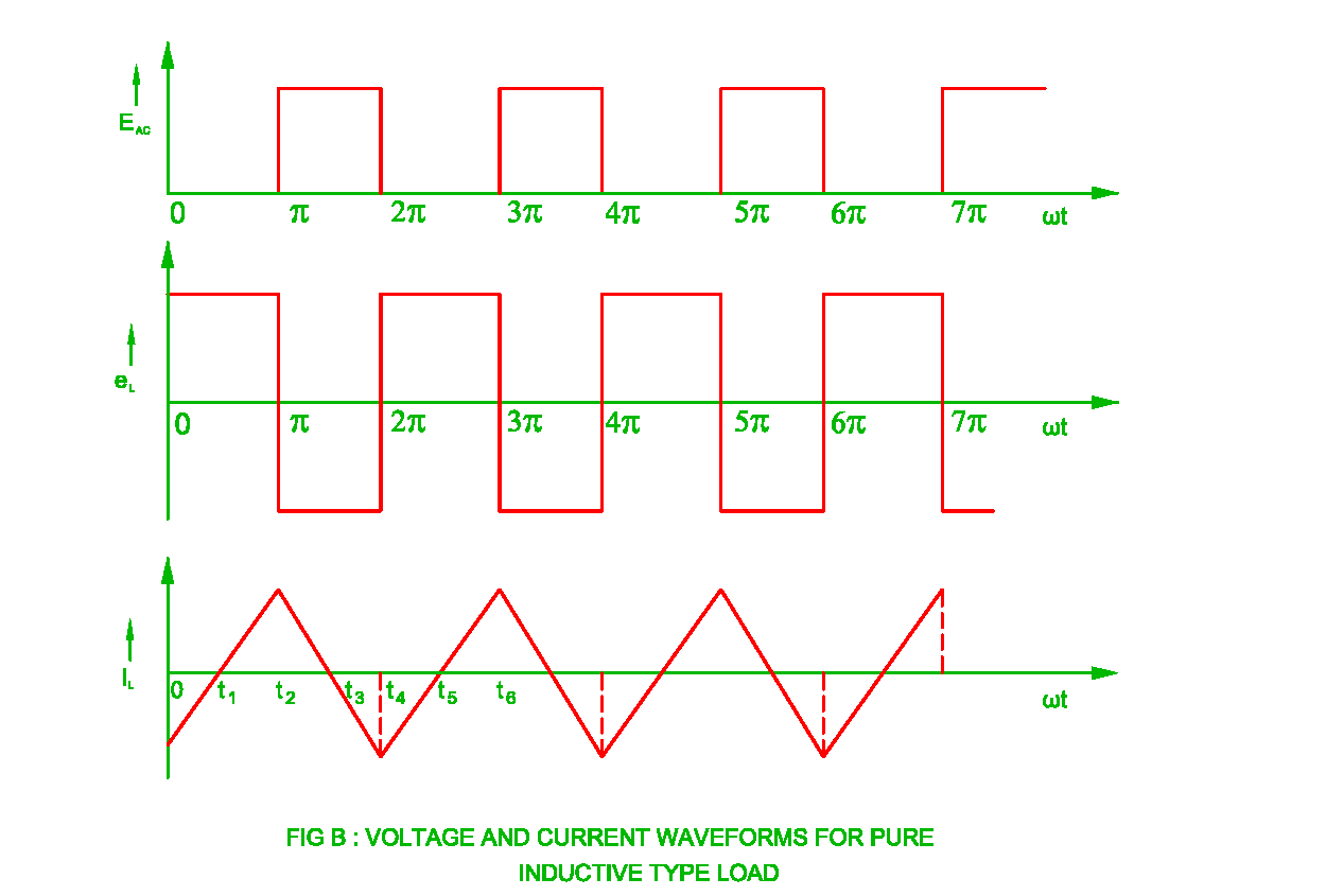
The current i l supplied to the single phase transistorised inverter is adjusted by the combination of variable dc voltage and inductance l.
And we previously learned about different types of inverters and built a single phase 12v to 220v inverter. A voltage source full bridge inverter is used at the output of the boost stage to convert the dc link voltage to sinusoidal output voltage. The inverter is made to give a voltage of 220v ac or 110v ac to the device connected with it at the output socket as a load. The voltage source inverter is defined as the inverter which takes a variable frequency from a dc supply.
Voltage source type inverters are commonly used for all home appliance and industrial power applications.
In the vsi, the switches are turned on and off at regular intervals to deliver rectangular pulses of voltage to each phase. Voltage source inverter (vsi) − the voltage source inverter has stiff dc source voltage that is the dc voltage has limited or zero impedance at the inverter input terminals. A voltage source mode using an output lc filter, and a grid connected mode with an output lcl filter. The input to the voltage source inverter has a stiff dc voltage source.
The figure below shows a voltage source inverter transistor.
Practically, dc sources have some negligible impedance. Stiff dc voltage source means that the impedance of dc voltage source is zero. Voltage source type inverters are easier to control than current source type inverters. The variable dc voltage source is converted into a variable current source by using inductance l.
This report focuses on dc to ac power inverters, which aim to efficiently transform a dc power source to a high voltage ac source, similar to power that would be available at an electrical wall outlet.
Aluminum heat sink= cut as per the required size; The resulting current waves are not influenced by the load. In this case, the magnitude of the inverter current and its waveshape is set by the value of the inductor and. Current source inverter 1) current source inverter.
An alternative approach is presented where only voltage.
There are two types of voltage inverters are currently used in market, first one is full bridge voltage source. Single phase voltage source inverter with simulink model: Inverter (dc/ac) control using a c2000™ microcontroller (mcu). The circuit is shown in the fig.
Then, the load voltage vector can be related.
The input voltage of the voltage source inverter remains constant, and their output voltage is independent of the load. In last article i have posted about forward converter design using simlink single phase voltage source inverter is a voltage source inverter that inverts the dc voltage into square wave ac or sine wave ac voltages. So these are classified into two types (voltage source inverter) and csi (current source inverter). Automobile battery= 12 volts/ 10ah.
These vtc circuits have traditionally depended on the use of a constant current source as part of their implementation in order to have good linearity.
This circuit generates a negative polarity voltage from a positive polarity one. Voltage source inverter (vsi) the inverter is known as voltage source inverter when the input of the inverter is a constant dc voltage source. The design supports two modes of operation for the inverter: The voltage source inverter can be connected to a parallel resonant load or ‘tank’ circuit.
But csis are not popular.
555 based polarity inverter circuits can only provide a few milliamps of current output. The line voltages are formed by connecting the line terminals of the motor to either the high or the low side of the dc bus voltage. A 3 phase inverter converts the dc voltage into 3 phase ac supply. Inverters are used for many applications, as in situations where low voltage dc sources such as batteries, solar panels or fuel cells must be converted so that devices can run off of ac.
Maximum input voltage is 18v, and output is up to 10w at 1 amp.
A rectifier (or converter) changes ac input to dc, followed by a dc link that serves as an energy storage circuit, and then an inverter switches dc back to variable frequency ac output. Voltage source inverters abbreviated as vsi are the type of inverter circuits that converts a dc input voltage into its ac equivalent voltage at the output. T1, t2 = 2n3055 power transistors. In csi, the input is a current source.
The output voltage space vectors generated by the inverter are defined by (6) where , , and are the phase to neutral voltages of the inverter (fig.
When the ac main supply is open, the inverter sensors consider it and pass this ac to the relay plus battery charging section. The waveforms of gate currents and output current i 0 are as shown in fig. One method employs a series connection of inductor and capacitor or lc circuit to couple the inverter current to the parallel resonant load, as shown schematically in figure 90. The classification of this can be done based on the source of supply as well as related topology in the power circuit.


