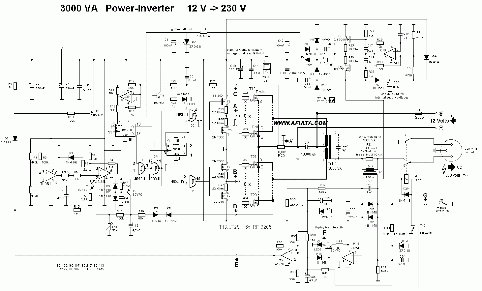
This is the circuit diagram of 2000w high power inverter circuit. An inverter of the kind you mention (which produces ac from dc) is way more complex and expensive, and a different circuit altogether. How to build a power inverter circuit needed components.
Transformerless Inverter Circuit Diagram Pdf Home Wiring
For better regulation, a 79lo xx series regulator can be used.
On my unit (2000 diplomat) the inverter powers 2 circuits, inverter 1 and inverter 2.
One is a more common inverter circuit diagram. Please careful with this circuit. Besides that, this circuit uses flyback transformer that can obtained from b/w or color tv or computer monitor. Simple 3 phase inverter circuit.
Use 24v dc supply for operation and connect 24v 5a or more than 5a transformer.
It is easier to obtain a regulated voltage than a regulated current, and voltage source type inverters can directly adjust the voltage applied to a load by Here is the first surprise; So that circuit can be eliminated from the equation. There are several ways to create an inverter when an engineer needs to convert dc to ac electricity.
This is a simple high voltage inverter circuit.
Few days ago, gohz made a 24v 2000w power inverter in home, sharing some design schematics and circuit diagrams. R1 (110 ohm/5w) and r2 (27 ohm/5w) are used to limit the current so as to reduce. The input voltage to be doubled is fed in at connector k1. The basic idea behind every inverter circuit is to produce oscillations using the given dc and apply these oscillations across the primary of the transformer by.
Automobile battery= 12 volts/ 10ah.
The circuit shown here only deals with dc, does not mess at all with ac. A zener diode may also be used to regualte the output voltage. Aluminum heat sink= cut as per the required size; 555 based polarity inverter circuits can only provide a few milliamps of current output.
A simple guide to selecting power mosfets.
A power inverter circuit is a circuit that converts dc power to ac power. When the ac main supply is open, the inverter sensors consider it and pass this ac to the relay plus battery charging section. This circuit shows how it is possible to use a trusty old ne555 timer ic and a bit of external circuitry to create a voltage inverter and doubler. T1, t2 = 2n3055 power transistors.
It 'flips' some voltage above ground to some voltage below zero.
This circuit is literally a voltage inverter, i.e. Simple modified sine wave inverter circuit. Voltage source type inverters are commonly used for all home appliance and industrial power applications. As a result, the circuit may require a large number of components to enhance the voltage.
Simple inverter circuit using arduino.
This circuit generates a negative polarity voltage from a positive polarity one. The inverter is made to give a voltage of 220v ac or 110v ac to the device connected with it at the output socket as a load. It is uses npn transistor type 2n3055. You can make the ac power be any level that you want and to any frequency that you want.
The microwave is on it's own circuit, inverter 2, which works fine.
In this circuit, the primary and secondary of transformer t1 is a 12.6 v to 220 v step down transformer, connected in the reverse format. The purpose of a dc/ac power inverter is typically to take dc power supplied by a battery, such as a 12 volt car battery, and transform it into a 120 volt ac power source operating at 60 hz, emulating the power available at an ordinary household electrical outlet. V+ can be anywhere from 4 to 16v. Simple inverter using ic 555.
This circuit used to invert low voltage to high voltage.
Maximum input voltage is 18v, and output is up to 10w at 1 amp. Voltage source type inverters are easier to control than current source type inverters. This is based on the mosfet3205. The maximum current output of the circuit is about 280ma, more than enough for a few op amps.
The circuit is an easy to build inverter that will boost 12 or 14 volts to any level depending on the transformer secondary rating.
The spwm accuracy of eg8010 was not high enough waveform, so the inverter output was not good enough as pure sine wave. We can achieve 220v ac at the output of just 12 volts.


