This is the circuit diagram of high power 1250va digital inverter with charger. Simple low power inverter circuit | 12v dc to 230v or 110v ac | diagram using cd4047 and irfz44 power mosfet. There are several ways to create an inverter when an engineer needs to convert dc to ac electricity.
Inverter Schematic Electronics Circuit
In the electronics or logic design subject, the inverter is also known as the not gate, which does nothing but logical negation.elaborating more, the inverter or not gate makes the high a low and the low a high.
This document describes inverter circuits used for motor control and other applications, focusing on pwm control.
The internet is flooded with single phase inverter circuit diagrams, but there are only few circuit diagrams of 3 phase inverter out there, a simplest possible 3 phase inverter is described here. The circuit will convert 12v dc to 120v ac. But such ics are not always readily available. Image of the pcb layout of this high power inverter circuit diagram is given.
It 'flips' some voltage above ground to some voltage below zero.
Aluminum heat sink= cut as per the required size; This is the power inverter circuit based mosfet rfp50n06. Using this circuit you can convert the 12v dc in to the 220v ac. It may be appropriate for you.
We can achieve 220v ac at the output of just 12 volts.
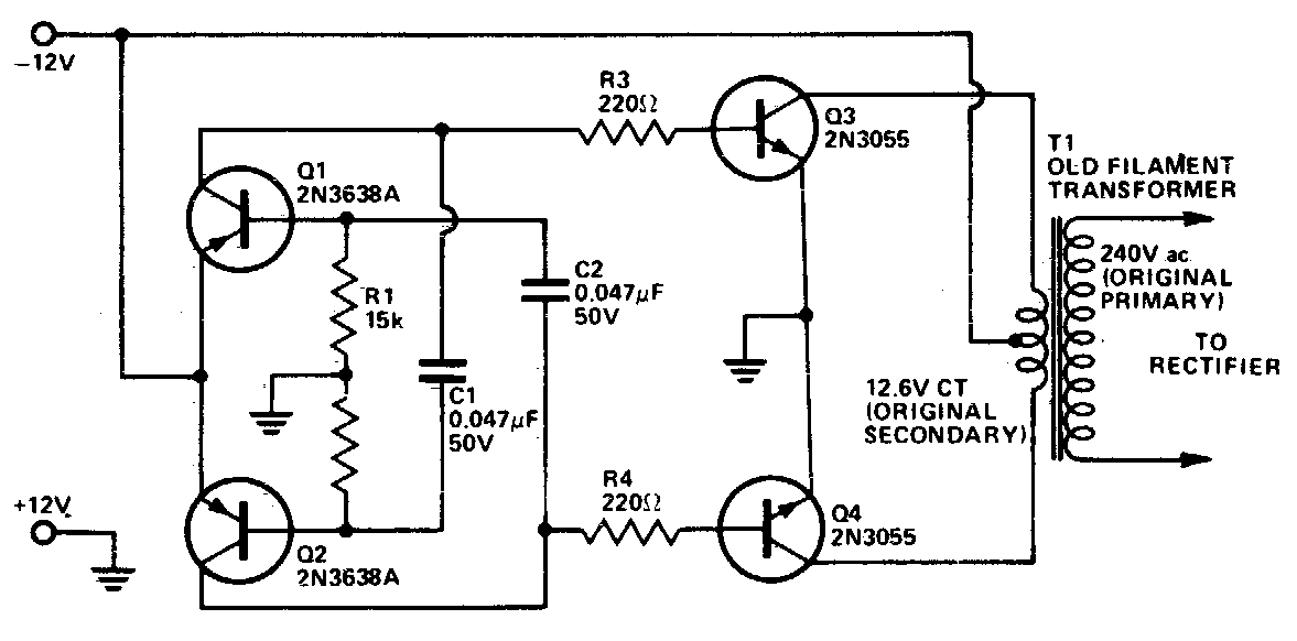
T1, t2 = 2n3055 power transistors. The spwm accuracy of eg8010 was not high enough waveform, so the inverter output was not good enough as pure sine wave. This basic inverter circuit can handle up to 1000watts supply depends the t1, t2 and transformer used. By doing simple modification you can also convert 6v dc to 230v ac or 110v ac.
This is based on the mosfet3205.
These circuits may be viewed below. Square wave voltage with duty cycle 25% for 230 volt rms (modified sine) As a result, the circuit may require a large number of components to enhance the voltage. Please careful with this circuit.
This is the circuit diagram of 2000w high power inverter circuit.
The input voltage to be doubled is fed in at connector k1. There are many basic electrical circuits for the power devices, a transformer, and switching devices. R2, r3, r4, r5 = 1k, t1, t2 = irf540; This is a kind of excellent performance power inverter for home circuit diagram, materials are easy to get, and the output power can reach 150w.
Three phase inverters require microcontroller design where the timings of the all three phases need to be precisely timed and executed.
One is a more common inverter circuit diagram. 0 41 1 minute read. This simple low power dc to ac inverter ( dc to ac converter) circuit converts 12v dc to 230v or 110v ac. Use 24v dc supply for operation and connect 24v 5a or more than 5a transformer.
Parts list for the above explained 150 watt inverter circuit diagram:
The rfp50n06 fets are rated at 50 amps and 60 volts. Wise tech august 14, 2017. This circuit shows how it is possible to use a trusty old ne555 timer ic and a bit of external circuitry to create a voltage inverter and doubler. This circuit is envisaged frequency in 300hz.
The circuit shown here only deals with dc, does not mess at all with ac.
R1 = 220k pot, needs to be set for acquiring the desired frequency output. Current and then amplify the voltage by using the step transformer. It uses only one 555 timer and a few other passive components, so it. Circuit diagram | 3000 watt power inverter 12v dc to 230v ac.
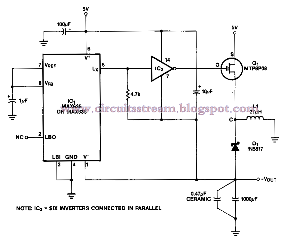
A negative supply voltage may be obtained with the use of a special inverter ic.
C1 = 0.01uf, c3 = 0.1uf; The present circuit is based on type 74hc14, which contains six. The dc alteration to an ac can be attained by stored energy within the dc source like the battery. Circuit 4047 is use to generate the square wave of 50hz and amplify the.
The inverter capable to handle loads up to 1000w, it’s depended on your power inverter transformer.
1000w power inverter circuit diagram: The main circuit of solar on grid inverter is presented in the following diagram. An inverter of the kind you mention (which produces ac from dc) is way more complex and expensive, and a different circuit altogether. Heatsink is required for cooling the mosfets.
The purpose of a dc/ac power inverter is typically to take dc power supplied by a battery, such as a 12 volt car battery, and transform it into a 120 volt ac power source operating at 60 hz, emulating the power available at an ordinary household electrical outlet.
Simple and practical 150w power inverter circuit. This circuit is literally a voltage inverter, i.e. Few days ago, gohz made a 24v 2000w power inverter in home, sharing some design schematics and circuit diagrams. Inverter 500w 12v to 220v by ic 4047+2n3055.
Before jumping into the inverter circuit diagram, it is necessary to know the logical symbol of the power inverter.
How to build a power inverter circuit needed components. This simple circuit is a good solution to the powering a dual supply op amp from a single battery problem. The purpose is to reduce the inverter transformer size and weight, output is square wave. Automobile battery= 12 volts/ 10ah.
Circuit diagram of 3000 watt power inverter 12v dc to 230v ac.
Full circuit diagram ferrite core inverter circuit.