The instance of exterior commutation inverter can seen here. In summary, with the controlled inverter circuit, the waveform of the output ac supply allows the motor to operate. Voltage source type inverters are commonly used for all home appliance and industrial power applications.
Pin on mkp
These converters are divided into six types of circuits or converters used in power electronics.
It contains two switches and each of its capacitors has a voltage output equal to $\frac{v_{dc}}{2}$.
The classification of inverters includes the types based on source, output, and type of load. Inverters are classified into two type’s namely single phase and three phases. Three main types of vfd are vsi, csi, and pwm. Inverters based on pv system type.
There are two types of single phase inverters − full bridge inverter and half bridge inverter.
These are the inverts that are cheaper than the inverter, as. These are typically from 25% to 50% maximum overload. Modes of operation wise classification. Simple inverter using ic 555.
Digital integrated circuits inverter © prentice hall 1995 noise in digital integrated circuits v dd v(t) i(t) (a) inductive coupling (b) capacitive coupling (c.
Leave a reply cancel reply. Know 5 types of inverters to choose from. The origins of electromechanical inverters explain the source of the term inverter. Considering the classification based on the mode of operation, inverters can be classified into three broad categories:
External commutation inverters are inverters for which energy is needed to off the scr is given through the exterior motor or supply.
Different types of the vfd. Most of the inverters available nowadays possess this pwm technology and are capable of. Types and classification of inverters sine wave inverters. Find every electronics circuit diagram here, categorized electronic circuits and electronic projects with well explained operation and how to make it procedure and then new circuits every day, enjoy and discover electronics.
Its pure sine wave output guarantees the safety and noiseless operations of the connected devices.
Pulse width modulated inverters (pwm inverter) replaced the older versions of inverters and has a wide range of applications. It is easier to obtain a regulated voltage than a regulated current, and voltage source type inverters can directly adjust the voltage applied to a load by Practically these are used in the power electronics circuits. Simple modified sine wave inverter circuit.
Voltage source type inverters are easier to control than current source type inverters.
The inverters are categorized in 2 main types through the commutation method employed for exterior commutation and self commutation. The panels are arranged in strings connected parallel to each other and then tied to the inverter. Simple inverter circuit using arduino. They are used in typical.
The most widely used type of tube was the thyratron.
Solar power generation technology has done a slow but a reasonable job of development of power inverters suitable for solar power. This type of inverter is the basic building block of a full bridge inverter. Simple 3 phase inverter circuit. When the ac mains power supply is not available,an oscillator circuit inside the inverter produces a 50hz mos drive signal.this mos drive signal will be amplified by the driver section and sent to the output section.mosfets or transistors are used for the switching operation.these mosfets or transistors are connected to the primary winding of the inverter.
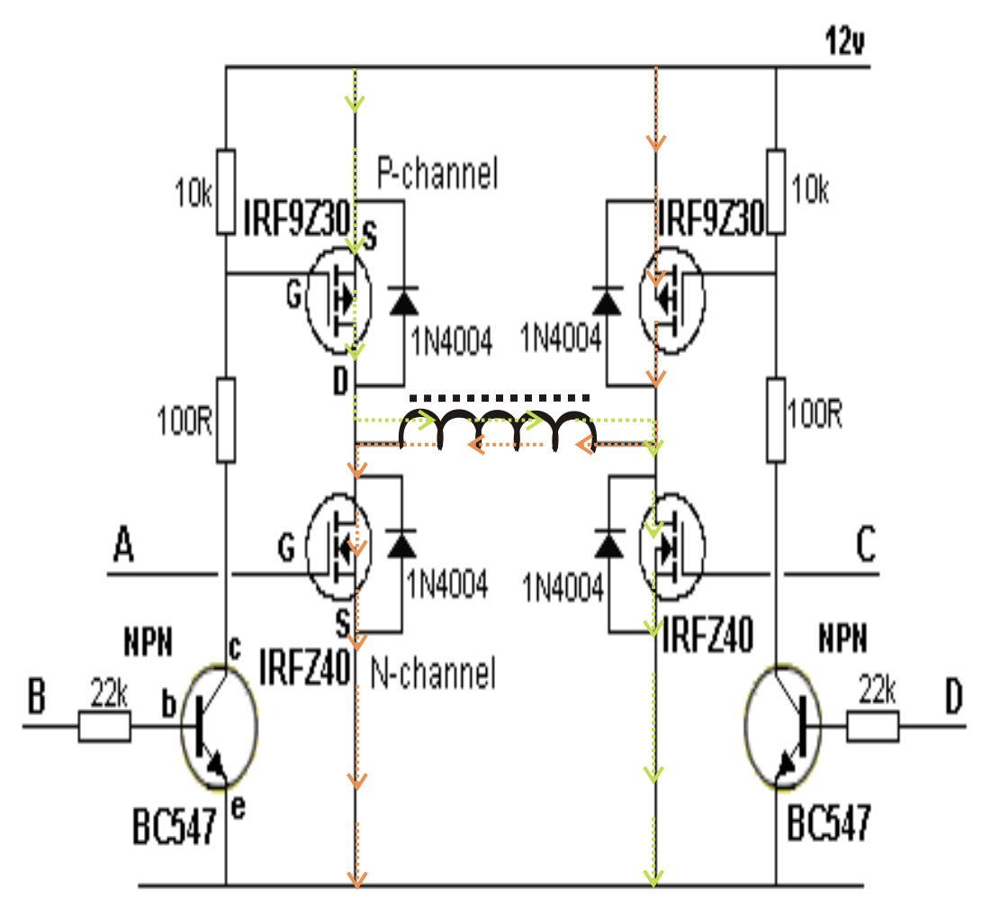
A full bridge inverter circuit consists of four transistors or mosfets arranged in a configuration resembling the letter h.
These types of solar inverters can broadly be categorized into 3 segments: It can be built with two switches where each one of its. These are the basic types of inverters with no more advanced features.