The materials used to build a tube light are given below. November 8, 2021 by larry a. The choke is in fact a large.
Find Out Here Led Fluorescent Tube Replacement Wiring
Connection instructions led tube light installation, ballast bypass cut the load and neutral wires from the ballast leaving a su˜cient amount of wire to connect back to the 110 vac power source.
The tube light does not work directly on power supply.
It shows the parts of the circuit as streamlined forms and also the power and signal connections between the. Remove the ballast from the Working principle of tube light. A wiring diagram is a streamlined traditional photographic depiction of an electric circuit.
Wiring diagram of single tube light installation with electronic ballast.
The circuit diagram for leds in parallel connection is shown in the following image. Led tube light ac led tubes led tube light electronic circuit projects It shows the components of the circuit as streamlined shapes, as well as the. Explore zeeshan ahmed mariner's photos on flickr.
Fluorescent ballasts can fail, requiring continued maintenance and eventual replacement or.
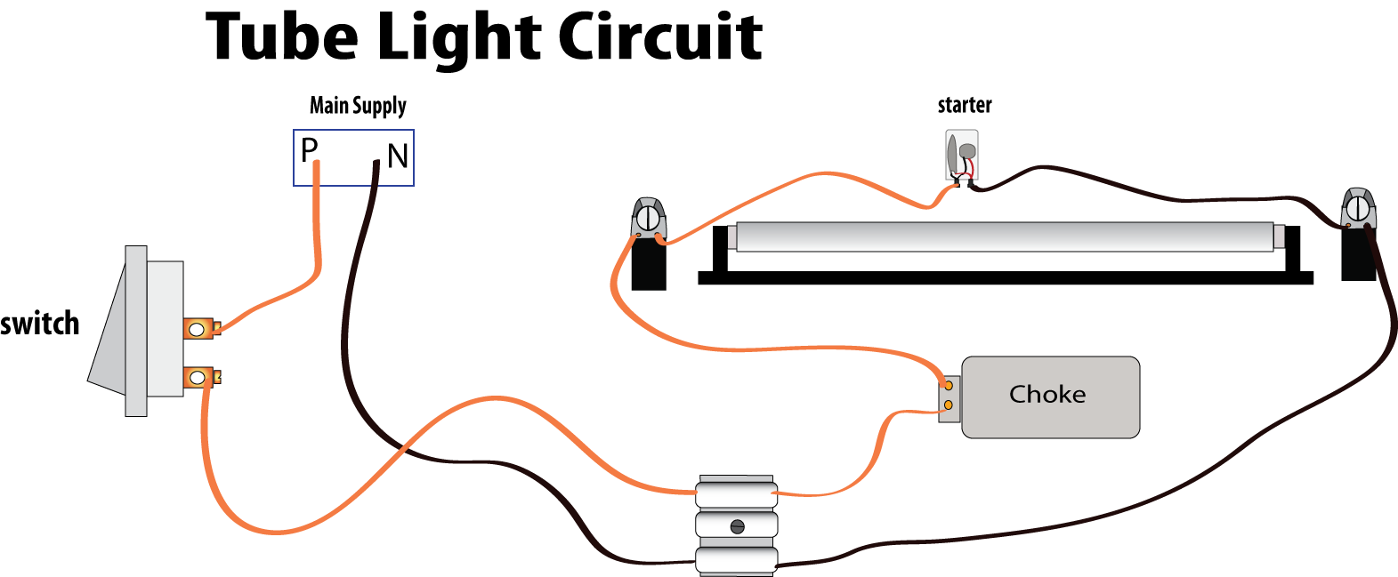
Connection and working we need tube light, ballast, starter and fluorescent light holders to make wiring connection. Working principle of a tube light material used inside the tube light. The wiring process of fluorescent tube lamp light with ballast starter is quite easy and simple. Here is one example of a tube light fixture consisting of a large heavy square “choke” or “ballast” and a small cylindrical “starter.” let’s try to understand how the whole system works.
The wiring process of fluorescent tube lamplight with ballaststarter is quite easy and simple.
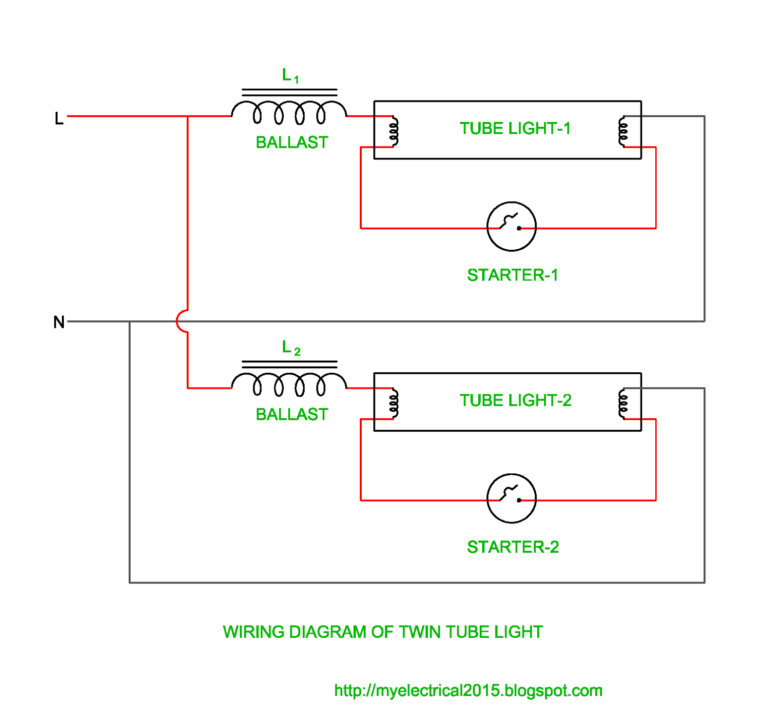
Working principle of tube light. Tube light connection diagram tube lights are most used light source and here tube light connection circuit and wiring diagram given with explanation. An led tube light is lighting device built using high efficiency leds for illuminating a premise where it is installed through the available ac mains supply. Wiring diagram here two tube lights are used, in our case each one is 20 watts, each tube light will have two filament with four terminals, connect starter element to any on side of tube light , after that link phase line to the ballast (choke) through switch.
The neutral wire from the main junction box is not carried to the switchboard it is connected to part 2 of the direct tube light.
Auxiliary electrical components along with tube light. A wiring diagram generally offers details regarding the family member placement and also. The starter is connected between two filaments, the ballast is connected between the main ac supply and one filament in the tube light. Main phase is given in part 1 by breaking with.
A wiring diagram is a simplified standard pictorial representation of an electrical circuit.
Zeeshan ahmed mariner has uploaded 174 photos to flickr. A wiring diagram usually gives counsel approximately the relative point of view and concord of devices. The tube light or fluorescent light is a low pressure mercury vapor gas discharge. One terminal of choke or ballast is connected to port 1 and another terminal is connected to pin 1 of terminal 1.
In most cases when we buy a fluorescent light it comes in a complete set with all wire.
From another terminal of the switch the wire is carried out up to tube light set up and connected to port 1. Bridge rectifier provides high voltage dc to the both end of tube. Making a real tube light connection following the above wiring connection, tube light, ballast, starter and fluorescent light required. This neutral wire is already connected to pin 1 of the terminal of the tube light with the help of a wire so the connection of this wire runs from part 2 to pin 1 of terminal 2 without any obstruction.
Cut back additional wiring on opposite side of ballast as the led tube lamp only requires power at one end.
Fluorescent tube light wiring diagram. Consumers not comfortable with or preferring to avoid electrical wiring work, lighting installations where electrician labor costs are high disadvantages: Each fluorescent tube has two filaments with four terminals; Please refer to the circuit diagram on the right as you read the following points:
Here two tube lights are used, in our case each one is 20 watts, each tube light will have two filament with four terminals, connect starter element to any on side of tube light, after that link phase line to the ballast (choke) through.
Variety of led tube light wiring diagram. One end of a starter is connected to pin 2 of terminal 1 and another end of the starter is connected to the pin 2 of terminal 2.