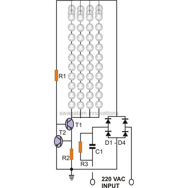
Rectified voltage(dc) is applied to both end of the tube. Jcb 3cx wiring diagram free download. A wiring diagram is a streamlined standard pictorial representation of an electric circuit.
Tube Wiring Diagram, http//bookingritzcarlton.info/tube
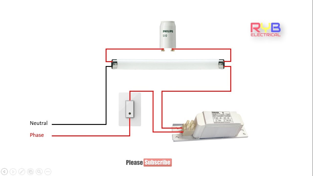
The starter is a small neon glow up lamp that contains a fixed contact, a bimetallic strip and a small capacitor.
Working principle of tube light
4 way switch wiring diagram electrical engineering electrical diagram electrical code. Using the diagram, you can perform analysis of. Bridge rectifier provides high voltage dc to the both end of tube. Low cost simple cfl lamp.
Led tubelight circuit diagram written by oto thursday, march 10, 2022 edit.
The tube light does not work directly on power supply. In my previous post i discussed the ic tl783 which is a 1.25v to 120v variable dc regulator ic. Electronics articles 8 aug a choke is connected in one end of the tube light and a starter is in series with the circuit. The choke is in fact a large.
In other words we can control (off or on) the bulb from upper and lower switches.
Tube light is not connected in the supply main directly. As shown in the diagram below, the ic 555 is wired in its most standard configuration of an astable multivibrator meaning in this mode the ic will. The purpose is the exact same. A circuit diagram, or schematic, is a picture of how the components in a circuit are connected together.
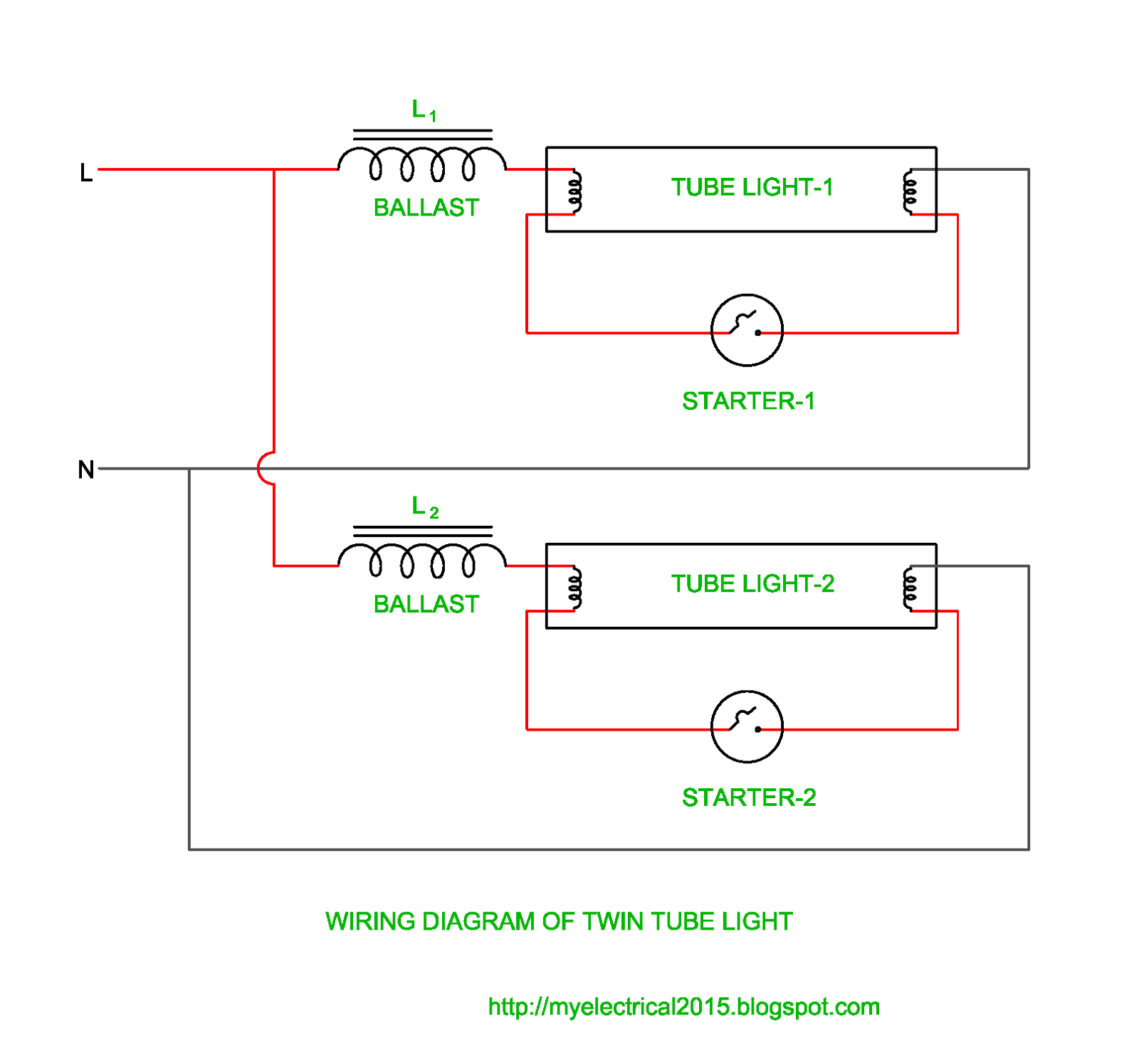
In most cases when we buy a fluorescent light it comes in a complete set with all wire.
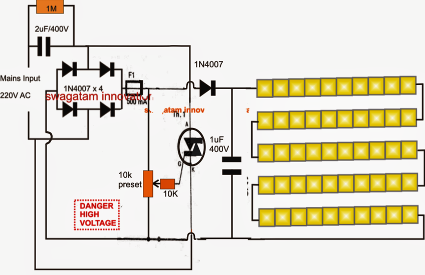
We can switch off and switch on the bulb from both switches at the same time. The circuit uses 30 numbers of 1 watt leds, and also includes a voltage and current control features. The diagram shows a straightforward configuration involving many leds, arranged in series and parallel. Using this circuit you can glow tubelight for extra six month.
A choke is connected in one end of the tube light and a starter is in series with the circuit.
Electronic ballast tube light wiring diagram connection and working we need tube. The fluorescent tube has two filaments with four terminals the starter is connected between two filaments the ballast is connected between main ac. This circuit replaced the choke and starter in an existing frame. Choke should be used in series with rectifier circuit for limiting current.
Emergency light with fluorescent tubes.
Please refer to the circuit diagram on the right as you read the following points: It needs some auxiliary components to work. This is a stair case circuit diagram by which we can control a bulb from two different places. The wiring process of fluorescent tube lamp/light with ballast, starter.
Fluorescent tube light ki wiring connection kaise ki jaati hai.
Tube light connection diagram shown here is suitable for common type fluorescent tubelight. The article explains a simple single ic led tube ligt circuit applicable for 110v/120v ac inputs. Tubelight circuit connection with diagram. Fluorescent tube light wiring diagram.
Tubelight circuit connection with diagram.
It shows the components of the circuit as simplified forms and also the power and signal links between the tools. When supply is provided,the starter will interrupt the supply cycle of ac. It may be electromagnetic ballast or electronic ballast. Wiring diagram motorguide brute 765 trolling motor.
The 3 segments should be connected in parallel to the house ac outlet.
A fluorescent lamp with a cylindrical tube is known as a tube light. When supply is provided the starter will interrupt the supply cycle of ac. A wiring diagram is a simplified standard pictorial representation of an electrical circuit. For converting ac to dc we have used a rectifier circuit.
An led tube light is lighting device built using high efficiency leds for illuminating a premise where it is installed through the available ac mains supply.
The circuit diagram shown above is quite simplified from basic tube light wiring diagram by adding a bridge rectifier. Here is one example of a tube light fixture consisting of a large heavy square “choke” or “ballast” and a small cylindrical “starter.” let’s try to understand how the whole system works. 110v compact led tubelight circuit.