4.1 basic considerations for 2d inverter circuits. Ask question asked 2 years, 7 months ago. Note that the led part of this circuit is very different from the other two circuits.
Transistor inverter circuit Basic_Circuit Circuit
You can make this circuit at home easily.
If you think that this circuit is not good enough.
The output signal (voltage) is the inverse of the input signal: This circuit used a 2n3904 npn transistor and, again, some resistors and capacitors to get the timing close to the two seconds wanted. Using inverter you can operate your led light, c. Inverters (not gates) are available on logic ics but if you only require one inverter it may be better to use this simple transistor circuit.
To this end, the cmos inverter is in several electronic devices while offering data around small circuits.
This part of the circuit provides the continuous square wave pulses needed for its working. The simplest inverters use switching devices which can interrupt the flow of current. Modified 2 years, 7 months ago. In this video, we are going to show you making a inverter circuit.
If a high signal is.
This inverter consists of arduino board which the heart of this built, buffer stage with couple of bjt npn transistors, couple of mosfets as usual like on any inverter and lastly a buzzer. Viewed 778 times 0 \$\begingroup\$ i have been trying to understand this question and i'm just not sure what equation to use for the collector current. How many transistors are in an inverter? One of the basic logic circuits is the inverter.
Bipolar transistor inverter circuit analysis.
It has a high collector output voltage of 230v. In the two circuit diagram below, just use 2 transistor, 2 resistors, and one transformer only. In this circuit, we will build an inverter with a transistor. Using inverter you can operate your led light, c.
This is an easy inverter circuit based upon 13007 transistor.
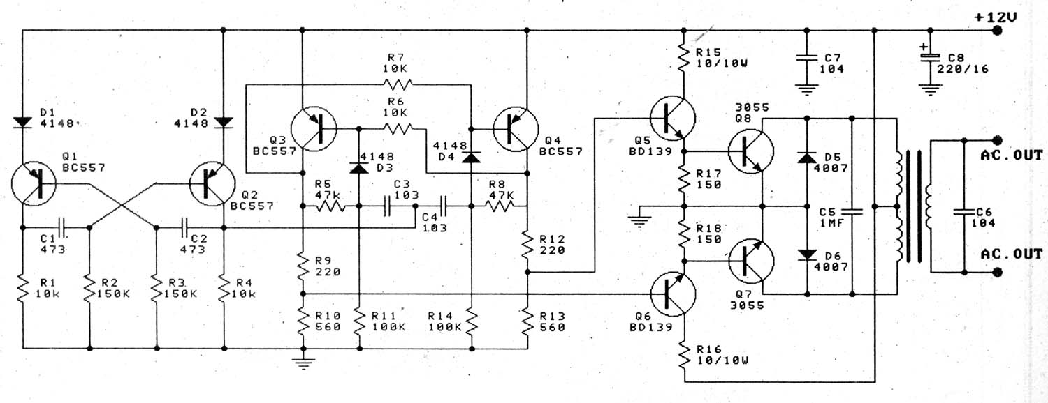
The main component of this inverter circuit is a ttc5200 npn power transistor. A simple transistor oscillator circuit. A basic cmos inverter uses 2 transistors. The transistors in the above circuit holds the most significant part in the working of this circuit where it was wired as a multivibrator.
To enable cmos circuits for 2d technologies the threshold voltage v th of the single transistors must be adjustable.
Also 500w inverter circuit for you. An interlock circuit for preventing simultaneous conduction of first and second complementary power transistors in a leg of an inverter, each power transistor having base, emitter and collector electrodes, the transistors being connected in series across a dc power source and being controlled in accordance with complementary base drive signals to cause an alternating output. They can convert 12vdc from battery to 220vac or 120vac to apply small light bulbs or lamps max 10 watts. An inverter is a component or device that inverts the state or logic level of a signal to the opposite logic level.
The above circuit is known as digital inverter since obtained output wave was a square wave.
I'm not sure if i need to be using an output voltage function of time? When it is fully on it is said to be saturated. In this video, we are going to show you making a inverter circuit. The buffer stage will amplify the feeble 5v signal from arduino pins and convert to 12v signal which is necessary to bias the mosfet to turn it on fully.
Thus, if a low signal is fed into an inverter, it flips it to a high isgnal.
Which transistor is used in inverter? This inverter is sweet for little loads like 15w led bulbs, mobile charger, and other electrical accessories. This is the circuit diagram of a 300w simple inverter. It is hard to find equipment.
You do not have it now.
The last circuit was the one requested: The circuit works with a push pull kind of operation where the q1 and q2 form a basic astable multivibartor for creating the basic 50 hz frequency. You can make this circuit at home easily. When the input is high (+vs) the output is low (0v).
Referring to the circuit design below we can see that the inverter circuit uses just 4 transistors, a transformer, and a battery to implement a ful 100 watt power output from a small 12v 10 ah battery.
The major applications of inverter circuits include;


