The major applications of inverter circuits include; Note that the led part of this circuit is very different from the other two circuits. When the input is logical 1, the output is logical 0.
Basic Inverter Circuit using Transistors Gadgetronicx
400v, 10 amp mosfet irf740 specifications.
This inverter circuit diagram which can change the voltage 12 volt.
It contains all the necessary features and libraries that will suffice you in your diagram making. It is just enough to make led b glow dimly. 1000w power inverter circuit diagram: You do not have it now.
It has 3 leads, the the source, gate and the drain.
The small base current controls the larger collector current. The output of an inverter is the opposite of its input. Heatsink is required for cooling the mosfets. The transistors in the above circuit holds the most significant part in the working of this circuit where it was wired as a multivibrator.
The rfp50n06 fets are rated at 50 amps and 60 volts.
Also 500w inverter circuit for you. This is the input signal that we want the transistor to invert. Many simple transistor configurations like, rain alarm, delay timer, set reset latch, crystal tester, light sensitive switch and many more have been discussed in this article. The maximum output power about 100 watts.
The transistor t1 remains conductive until the breakdown occurs.
In digital logic, an inverter or not gate is a logic gate which implements logical negation. In this example circuit, the input is a push button switch and the output is an led light. Sinusoidal pulse width modulation, h bridge and low pass lc filter to make pure sine wave inverter circuit diagram. There are several ways to create an inverter when an engineer needs to convert dc to ac electricity.
This circuit is a mini inverter circuit using power transistor 2n3055 as the main components without ic.
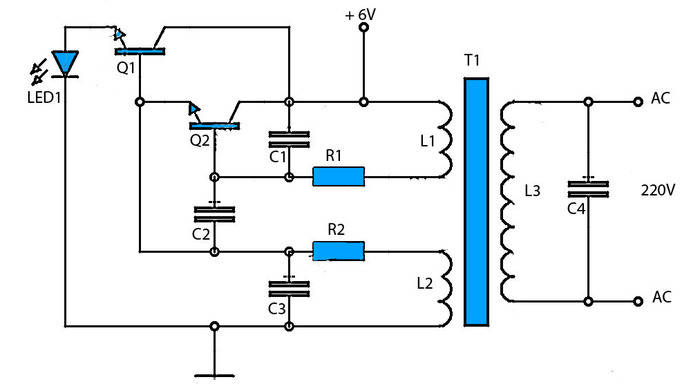
We will show exactly how this works in detail below. This circuit used a 2n3904 npn transistor and, again, some resistors and capacitors to get the timing close to the two seconds wanted. Terminal circuit boards are detachable and replaceable with a large variety of optional circuit boards. In the two circuit diagram below, just use 2 transistor, 2 resistors, and one transformer only.
They can convert 12vdc from battery to 220vac or 120vac to apply small light bulbs or lamps max 10 watts.
The transistor amplifies this small current to allow a larger current to flow through from its collector (c) to its emitter (e). If you think that this circuit is not good enough. You can use edrawmax for making a circuit diagram of an inverter. The circuit demonstrates the use of a transistor as a inverter.
To this end, the cmos inverter is in several electronic devices while offering data around small circuits.
One is a more common inverter circuit diagram. The picture above is our inverter schematic. 3 phase inverter circuit diagram the internet is flooded with single phase inverter circuit diagrams, but there are only few circuit diagrams of 3 phase inverter out there, a simplest possible 3 phase inverter is described here. It can be converted 12vdc to 220vac.
Someone use it in a car or the high mountain etc.
The diagram shows the two current paths through a transistor. Sine wave inverter circuit digram with code igbt (insulated gate bipolar transistor) module is a device required for inverter use in many types of industrial equipment, and had driven the trend towards high currents and high. In this compilation of simple transistor circuits (schematics) you will come across many small very important transistor configurations,. The frequency of the above pulse.
Cheap dc to ac inverter circuit using power transistor:
The inverter capable to handle loads up to 1000w, it’s depended on your power inverter transformer. When the switch is closed a small current flows into the base (b) of the transistor. When we supply 12v to this simple inverter circuit one of the transistors goes into the conductive stage. Here we are using the 2sc1815 in an astable multivibrator configuration.
The above circuit is known as digital inverter since obtained output wave was a square wave.
As a result, the circuit may require a large number of components to enhance the voltage. This is the power inverter circuit based mosfet rfp50n06. Inside an igbt inverter welder transistor, foreign design: Simple transistor circuits for new hobbyists.
This time we used the larger power transistor 2n3055, and only two resistors are used, and the power of the resistor is selected to be larger, so the output power of the circuit will be corresponding.
This inverter circuit uses two ic ne555 and sn74ls112 and 10 2n3055 transistor with some other components. This software is used for diagram making. A simple transistor oscillator circuit. In this circuit, we will create an inverter with a transistor.
It is hard to find equipment.
Use edrawmax for circuit diagram creation. This is the circuit diagram of a 300w simple inverter. This part of the circuit provides the continuous square wave pulses needed for its working. The heart of this circuit is a 2sc1815 transistor.
The input signal attaches to the gate of the transistor.
We can achieve 220v ac at the output of just 12 volts. The above figure uses a 1w 400 ohm resistor. The last circuit was the one requested: It is designed for you that need to use appliances outdoor or no electricity.