Transformerless inverter circuit arrangement, in particular for coupling a photovoltaic system to the grid. A ups has an inverter as part of the design. Besides, it has the ability to generate the boosted voltage without the need of magnetic.
Compact, Ferrite Core Transformerless Inverter Circuit
This inverter can easily operate on higher switching frequencies due to low switching loss.
For the lower power level transformerless inverters, most of the innovative topologies try to use super junction metal oxide semiconductor field effect transistor(mosfet) to boost efficiency, but these mosfet based inverter topologies suffer from one or more of these drawbacks:
In order for transformerless inverters to comply with nec specifications specially designed and more expensive pv wire must be used. They do this by using a large bank of batteries to create a large dc voltage. Transformerless inverters do not have electrical isolation between dc and ac circuits. The proposed transformerless inverter design is a modified sine wave type which is better than square wave counterpart.
A common mode model, of the transformerless converter can be derived from the circuit shown in figure 6 (gubía et al., 2007).
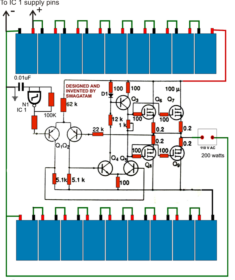
8 rows transformerless inverter block diagram. Since an inductor […] 3kva transformerless inverter circuit | circuit projects. So you can select as you want. Results of simulation and practical implementation of the proposed circuit prove the accuracy of the circuit performance.
Transformerless single phase inverter category:
The high efficiency dc to dc boost converter is the key. A little innovative thinking shows that the above cumbersome design can be replaced by just batteries and a small circuit for implementing all the necessary actions of an efficient compact transformerless ups circuit. Mosfet failure risk from body diode reverse recovery, increased conduction losses due to more. Joined apr 7, 2010 14.
Transformerless inverter circuits circuit 1000 watt modified sine wave switching dc ac 12v make your own full homemade 2000w power with 5kva ferrite core 2kva all about simple sinewave self charging off grid pure 1kva diagram solar 5000w 48v pwm based on sg3524 inverters 500w to 220v tied if a higher load single phase 230v 250w china customized home.
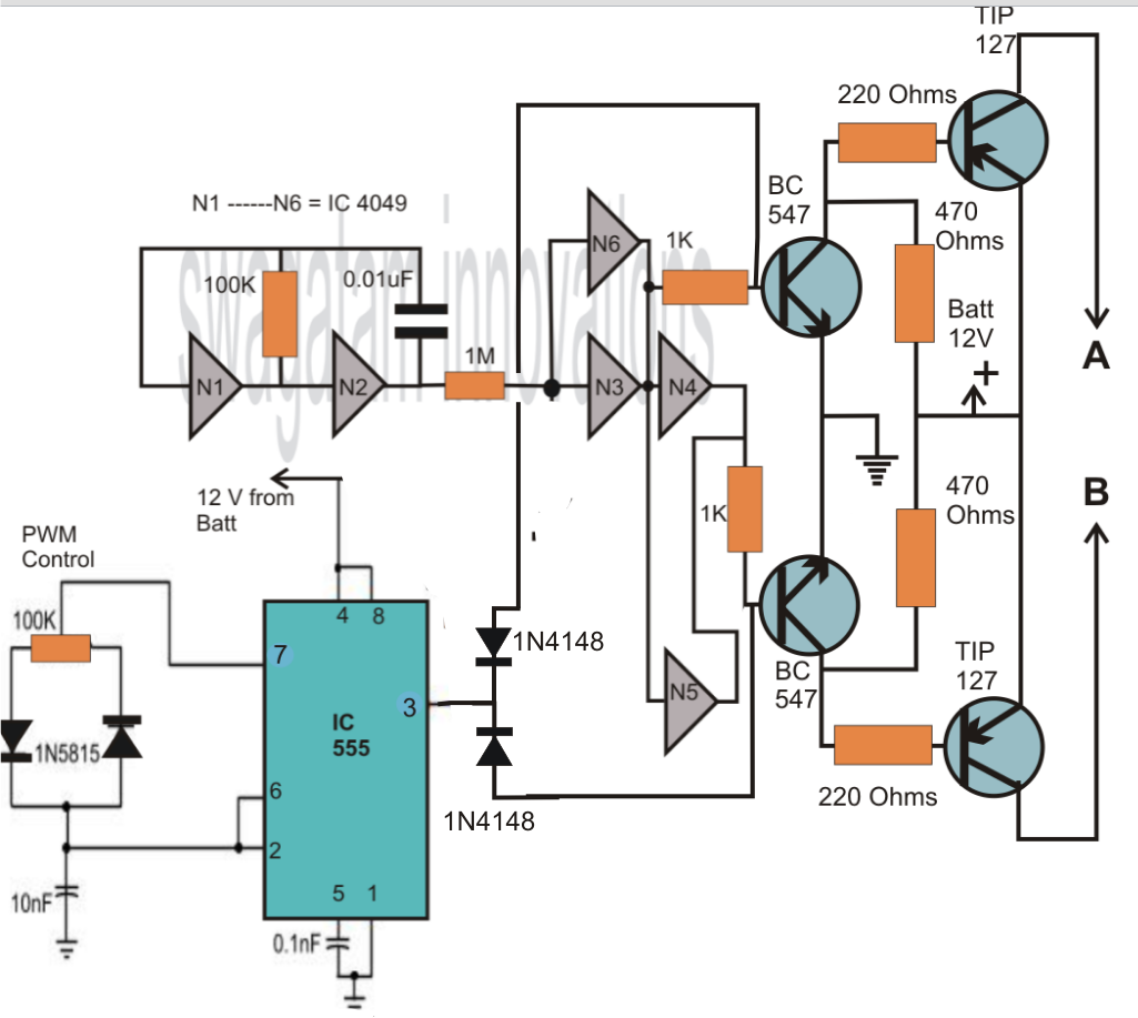
The common mode model is shown in figure 7 , as it can be observed, there are two main pulse voltage sources named v cmv which corresponds to the cmv and v s1 , which represent the influence of the differential mode voltage (v dmv ) in. Hopefully, it will be useful to you. There are three circuits, as follows. In this post we are going to construct a transformerless inverter circuit which can be power via solar panels and also using batteries.
Since an inductor based transformer is not employed, the input dc is normally equal to the peak value of the ac generated at the output of the inverter.
A voltage regulator can help regulate power fluctuations based on power loss and gain from sunlight fluctuations. It consists of three main circuits; However the design also a few. A transformerless inverter is lightweight, because of the absence of transformer.
This may raise some grounding and / or lightning protection concerns.
Transformerless inverters are increasing in popularity in european and australian markets. Electricity is becoming a central need of human being. They use a capacitor instead of a bigger transformer. Sg3524 pwm control ic based on the dc to ac inverter circuit transformer change and the number of transistors compared to the 250w 5000w power between can give to developing an open circuit and adding a lot can be.
Of transformerless inverter inverter circuit that converts a dc input into ac without depending on an inductor or a transformer is called a transformerless inverter.
They use the transformerless power supply circuit. As the name suggests, an inverter circuit that converts a dc input into ac without depending on an inductor or a transformer is called a transformerless inverter. Looking at the below shown solar based transformerless inverter circuit diagram we can see that it basically consists of three main stages viz. Even, in most led light bulbs.
Such inverters occupy enormous spaces, require bigger batteries and are immensely expensive.
An improved gate driver circuit would help somewhat, but very little due to the low frequencies involved. A transformerless solar inverter circuit design eliminates a transformer by using high voltage mosfets to harness solar energy. Today, we will learn these transformerless power supply circuit. Transformerless single phase inverter quantity.
For the pv generation system, the power converter is the most essential part for the efficiency and function