Tl494, ncv494 www.onsemi.com 6 applications information description the tl494 is a fixed−frequency pulse width modulation control circuit, incorporating the primary building blocks required for the control of a switching power supply. So the efficiency of the circuit becomes (71.6958 / 82.9539) x 100 % = 86.42 %. If we want to make 100 watts inverter we can use this circuit diagram.
Inverter Circuit Diagram Using Tl494 Home Wiring Diagram
5 amps of current settings can be made.
Which using a tl494 (switchmode pulse width modulation control ic) is a base for control dc motor with pulse.
Modulation of output pulses is accomplished by comparing the sawtooth waveform created by the internal oscillator on the timing capacitor (ct) to either of two control signals. Motor drive circuits made with tl494 pwm control integrated low current p channel n channel and np channel mosfetler reinforced different circuits without mosfet schematic drawings prepared with splanes. 30 volt power supply voltages from 1 to 20. (see figure 1.) an internal−linear sawtooth oscillator is frequency− programmable by two external.
Stay tuned and don't forget to hit that subsc.
I have designed a proteus simulation on how to generate pwm signals and how to design a buck converter. Power inverter with tl494 and h bridge power mosfets 900watt 12 240v electrical circuit diagram electronic schematics circuit diagram. A pwm inverter is a type of circuit that uses modified square waves to simulate the effects of alternating current ac which is suitable for powering most of your household appliances. Absolute maximum current draw in my testing table.
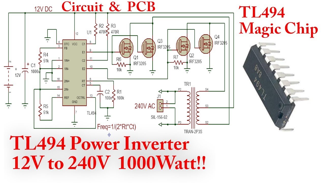
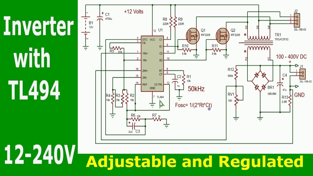
12 volt to 220 volt inverter circuit diagram.
12v dc motor speed control pwm circuit using tl494. You can use 2x100w rms stereo or 200w rms mono, which can be controlled by bridge. Tl494 is a pwm control or generation integrated circuit. This is a 12v dc motor speed control pwm circuit.
When tl494’s in a dcdc my attention.
Pwm inverter circuit using tl494. Make 2000w inverter sine use 20 mosfet. Also used in many applications lm2576t adj (adjust) made with integrated dcdc 1. This post for, how to make an inverter?
Tl494 is a pwm control or generation integrated circuit.
In this episode i'll show you how to make your own 3kw inverter with just a handful of components. Scooter motor driver circuit pwm control at the output made with tl494 ic 2 irf3710 mosfet are controlled with irs2104 mosfet driver. The loss in the circuit is due to the resistors for powering the tl494 ic and. 0 283 less than a minute.
The pcb design, which resembles the project ” rms 250w auto amplifier jbl filter smps ei35 sg3525 ” that was previously shared, is a fairly regular auto amplifier circuit.
From the above image, it can be seen that the maximum current draw from the circuit is 6.96 a it's almost. Tl494 is used in many applications. 200w auto amplifier circuit tip147 tip142 tl494 ei33 dc dc schematic circuit diagram. The output stage is enabled during the time when the
There tl494 50v voltage and current with the tuned circuit diagram is very similar.
This is a 12v to 220v inverter circuit dc to ac voltage inverter using the circuit tl494 ic and mosfet transistors irfz44n. Stay tuned and don't forget to hit that subsc. 200w auto amplifier circuit tip147 tip142 tl494 ei33 dc dc schematic circuit diagram. It can be used in dc to dc converter circuits.