In this post we learn how to make a simple microprocessor arduino based 3 phase inverter circuit which could be upgraded as per user preference for operating a given 3 phase load. Three phase sine wave inverter is used in many applications. An arduino three phase inverter is a circuit which produces a 3 phase ac output through a programmed arduino based oscillator.
Three Phase Inverter Circuit Diagram DIY Electronics
It is used in many industrial as well as domestic applications.
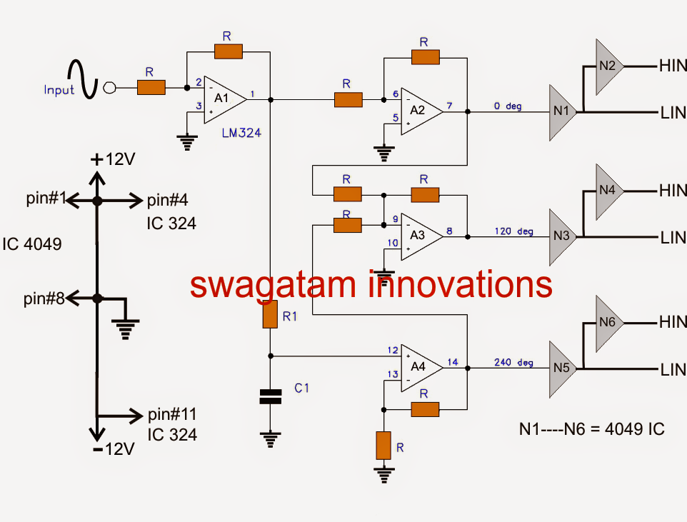
The circuit consists of an arduino which generates the 3 phase waveform with 120degree electrical phase difference between each individual waveform.
What is three phase inverter? They are durable and sustainable to offer consistent service relentlessly without the chances. In the above 3 phase generator circuit (second last diagram) using a sine wave. This project presents the design and simulation of 3 phase power inverter.
The inverter switches each has a ratio of 50% and switching occurs after every t/6 of the time t (60° angle interval).
These 3 phase inverter circuit are equipped with the latest technologies and come with distinct power capacities to serve your purpose with ease. Single phase inverter and three phase inverter. Three single‐phase inverters operating together, or one three‐phase inverter. Three phase inverters can be realized in two ways:
Igbt is a mosfet and gtr composite device, so it has work fast, big input impedance, simple driving circuit, simple control circuit, higher operating frequency, large element capacity.
The circuit concept the oscillator and the pwm stage. Program codefor 3 phase inverter circuit: In this project, three phase sine wave inverter is designed using atmega2560 microcontroller. You can select from the existing 3 phase inverter circuit models on the site or go for completely customized versions of these products.
A three phase inverter employs 6.
This document describes inverter circuits used for motor control and other applications, focusing on pwm control. A 3 phase inverter converts the dc voltage into 3 phase ac supply. This is why you remain in the best website to look the unbelievable book to have. Three phase inverter are classified in two types:
It is usually controlled in a bipolar manner.
The circuit consists of an arduino which generates the 3 phase waveform with 120degree electrical phase difference. As this 3 phase inverter circuit diagram motor controller, it ends in the works mammal one of the favored books 3 phase inverter circuit diagram motor controller collections that we have. A single phase inverter takes the dc voltage as input and converts it to single phase ac voltage while a three phase inverter converter converts the dc voltage into three phase ac voltage. The ic 4047 is wired as a standard flip flop output generator at the rate of the.
They are used to drive bldc and other 3 phase motors.
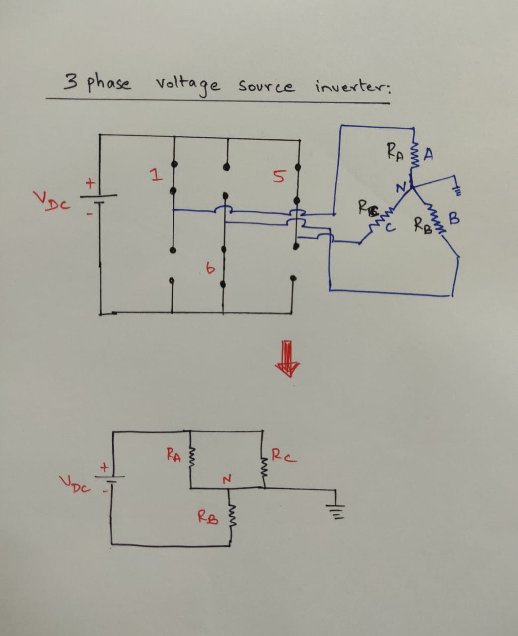
3 phase inverter circuit diagram the internet is flooded with single phase inverter circuit diagrams, but there are only few circuit diagrams of 3 phase inverter out there, a simplest possible 3 phase inverter is described here. Following is a schematic for a three‐phase inverter with a 3‐phase, wye connected, resistive load attached: The three phase inverter is almost always the better choice. Download scientific diagram | 1, three phase inverter circuit from publication:
In all for the circuit, we require six switching devices.
Three phase sine wave inverter is more often used in power electronics application where power requirement is greater than 10kva. The pwm of phase a, b, and c is usually jointly controlled by a triangular wave carrier v. Based on the type of supply, there are two types of inverters: We have already studied an effective yet simple.
The voltage source inverter is that the input dc energy in the inverter circuit is provided by a stable voltage source.