In this article, we will discuss 3 phase inverter circuit which is used. To construct three phase inverter circuit and to analyze the different output frequency waveforms. You could buy guide 3 phase inverter circuit diagram motor controller or acquire it as soon as feasible.
Three Phase Bridge Inverter Explained Electrical Concepts
Three phase inverter convert a dc voltage into three phase ac voltage.
In this circuitry, the 6 scrs are linked in this sequence scr1, scr6, scr2, scr4 scr3 scr5, and capacitors from c1 to c6 offer the commutation needed through scr.
The circuit diagram of three phase bridge inverter consists of minimum of 6 scr and 6 diodes. Three phase inverter circuit diagram. Two types of control signals can be applied to run this circuit •. The control section of the microprocessor is responsible for the control of the vfd operations.
This capacitor reduces the harmonics feedback to the source.
Three significant sections constitute the block diagram of a vfd. Arduino 3 phase inverter circuit with code arduino esquemas eletronicos inversor solar. Three phase inverter design/circuit diagram. This is why you remain in the best website to look the unbelievable book to have.
Igbt is a mosfet and gtr composite device, so it has work fast, big input impedance, simple driving circuit, simple control circuit, higher operating.
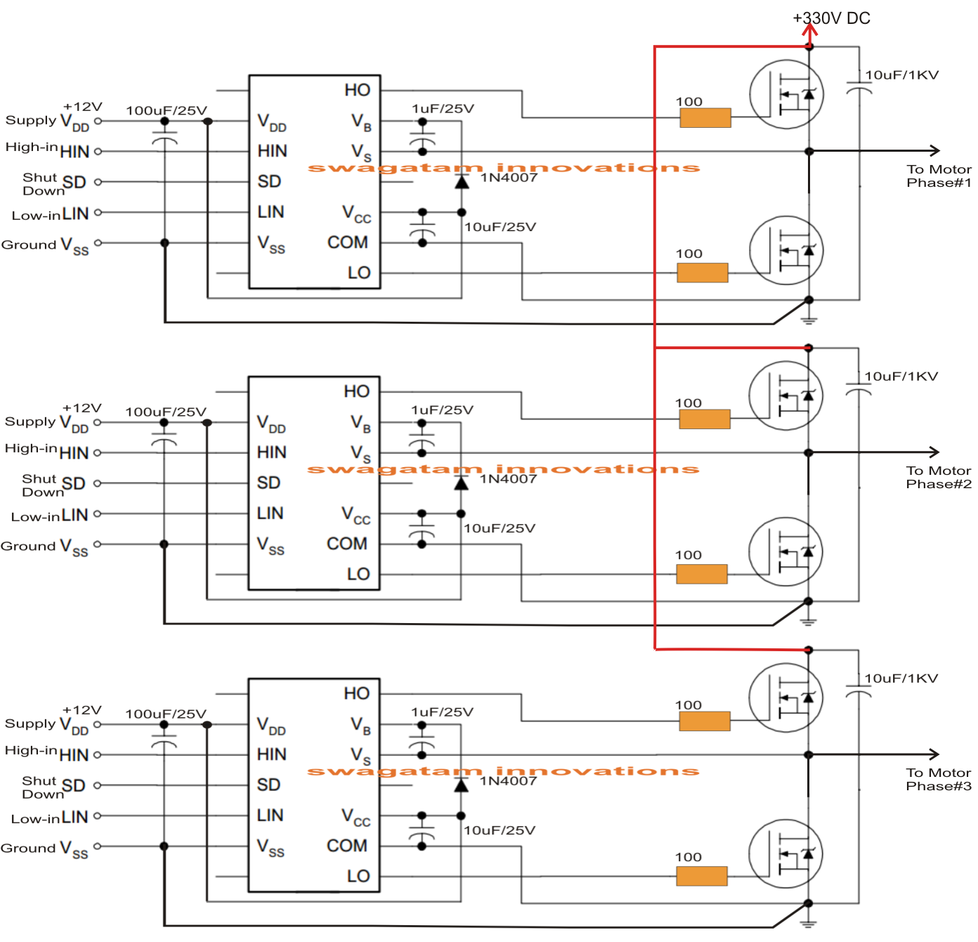
A three phase inverter employs 6 transistor switches as shown above which are driven by pwm signals using gate driver circuits. Here a large capacitor is connected at the input side in parallel with vs to make input dc voltage constant. In industrial application three phase inverter are more. If we draw the voltage waveforms for each phase then we will have a graph as shown in the figure.
Scribd is the world's largest social reading and publishing site.
It’s basics and circuit diagram. Each part ought to be placed and connected with other parts in… The power consumption section changes the ac voltage to dc. The gate pulse of 1 & 4, 3 & 6 and 5 & 2 are totally opposite in this mode of operation.
Three phase inverters require microcontroller design where the timings of the all three phases need to be precisely timed and executed.
We will have a brief look at the three phase transformer working and we will construct a three phase transformer using three “single phase transformer” by combining the windings in delta and start connections. July 26, 2021 rashikagupta1985 power electronics. Read free 3 phase inverter circuit diagram motor controllergetting this info. In the graph, we can see three voltage waveforms are out of phase with each other by 120º.
A basic 3 phase inverter includes 3 single phase inverter switches where each switch can be connected to one of the 3 load terminals.
Circuit diagram of three phase bridge inverter: We will have a brief look at the three phase transformer working and we will construct a three phase transformer using three “single phase transformer” by combining the windings in delta and start connections. The internet is flooded with single phase inverter circuit diagrams, but there are only few circuit diagrams of 3 phase inverter out there, a simplest possible 3 phase inverter is described here. Three phase inverter ¦ introduction, basic working, circuit diagram.
Get the 3 phase inverter circuit diagram motor controller member that we offer here and check out the link.
In all for the circuit, we require six switching devices. As this 3 phase inverter circuit diagram motor controller, it ends in the works mammal one of the favored books 3 phase inverter circuit diagram motor controller collections that we have. Sinusoidal pwm signal generation technique for. Solar 3 phase inverter circuit arduino circuit projects electronic circuit projects.
Egp3000w three phase pure sine wave inverter power base plate pcb board ups eps ebay sine wave circuit diagram electronics circuit.
The only difference is in the gate pulse of switches.