As this 3 phase inverter circuit diagram motor controller, it ends in the works mammal one of the favored books 3 phase inverter circuit diagram motor controller collections that we have. The ucc21520 has many features to design a reliable three phase inverter. Get the 3 phase inverter circuit diagram motor controller member that we offer here and check out the link.
Draw your wiring Pure Sine Wave Inverter Circuit Diagram Pdf
Three phase inverters require microcontroller design where the timings of the all three phases need to be precisely timed and executed.
This is why you remain in the best website to look the unbelievable book to have.
3 phase generator wiring diagram pdf wiring diagram line wiring diagram. This board performs the function of dc/ac conversion. Block diagram of inverter” 3.1 ac source an ac source is ordinary supply of rectifier, which has any frequency and voltage rating.which is practically constant supply of 3 phase or 1 phase. It comprises of two boards:
Ups inverter diagrams pdf free 3000w power 12v to 230v digital circuit diagram 4 simple uninterruptible supply sinewave using pic16f72 homemade solar m 100 watt offline engineering projects electronic abc home facebook sine wave build 200w 500 with battery circuits 2000w homage schematic microtek how an works.
Thyristors 1 & 2 conduct 60° van = , , v cn = mode 3: Microtek inverter circuit diagram pdf electrical learner. The gate drive circuit comprises of three ucc21520 devices, which are dual igbt gate drivers. Thyristors 1 & 6 conduct 0 v an = , , v cn = 0 mode 2:
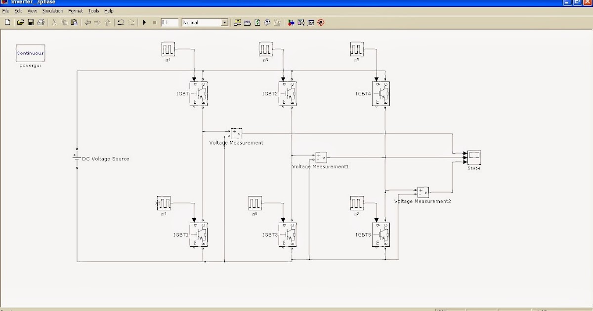
In the circuit, a bridge like circuit comprised of igbt transistor is used which converts dc to ac.
120 240 vac single how is the excitation controlled on a brushless ac quora pdf design to static power converter simple inverter circuit homemade projects dse7310 mkii dse7320 installation instructions block four wire compensation system scientific 7 wires 5kw avr. A power stage module and a control module. Before this block there is switch to operate supply and protection system by fuse. Three phase inverter ¦ introduction, basic working, circuit diagram.
Read free 3 phase inverter circuit diagram motor controllergetting this info.
The three phase inverter with synergy technology inverter (referred to as 'inverter' in this manual ) efficiently converts dc power from the modules into ac power that can be fed into the main ac service of the site and from there to the grid. Three phase inverter circuit diagram. This document describes inverter circuits used for motor control and other applications, focusing on pwm control. 3 phase distribution board wiring diagram pdf wiring diagram is a simplified tolerable pictorial representation of an electrical circuit it shows the components of the circuit as simplified shapes and the aptitude and signal contacts amongst the devices.
For these three modes of operation:
Three phase 3 phase distribution board wiring diagram. You could buy guide 3 phase inverter circuit diagram motor controller or acquire it as soon as feasible. Three phase inverter circuit diagram diy electronics projects power of an igbt based single full bridge scientific simple 3 homemade 120 degree and 180 conduction mode 12v dc to 220v ac pcb make your own sine wave explanation pdf design implementation a specific grid tie for agent microgrid smps welding easy sg3525 circuits explored overcur short. Alternatively, a three phase inverter uses two input dc sources, using 6 igbt transistors to convert dc voltage into ac voltage and the output of such a circuit will be a three phase ac waveform with a phase difference of 120.
As you can see this six mechanical switch setup is more useful in understanding the 3 phase inverter working than the cumbersome thyristor circuit.
Dc/ac pure sine wave inverter jim doucet dan eggleston jeremy shaw mqp terms abc 20062007 advisor:


![NO!APEC TV [37+] Draw The Schematic Diagram Using Bis](https://i2.wp.com/electronics-project-hub.com/wp-content/uploads/2020/10/corrected-3-phase-1024x645.jpg)