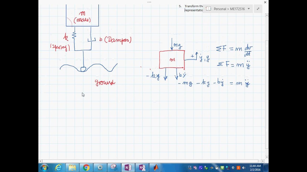
Obtain equation of motion from free body diagram: Simulink block diagram of the suspension system figure 5: The inputs are set point, a point at which the ball should be suspended and the reference signal or
Block diagram of the active suspension system. Download
A diagram of this system is shown below:
A vehicle suspension system can be modelled by the block diagram shown in figure below:
A vehicle suspension system can be modelled by the block diagram shown in figure 1 analysing a simple system body mass wheel figure 1: Analysedmolem a vehicle suspension system can be modelled by the block diagram shown in figure 1 below body road figure 1: The state space approach was used to develop the mathematical model of an active suspension system from its. Lastly, the system was further more analyzed by creating a block diagram and using simulink to see the behavior of the system.
Many people can understand and understand schematics generally known as label or line diagrams.
* body mass (m1) = 2500 kg, * suspension mass (m2) = 320 kg, * spring constant of suspension system(k1) = 80,000 n/m, * spring constant of wheel and tire(k2) =. The tyre is modelled by the spring and dashpot (damping system with. The tyre is modelled by the spring and dashpot (damping). Construction of air suspension :
2014 j b ashtekar and a g thakur, 2014 table 2:
This diagram shows the electrical system (yellow),. The free body diagram was drawn as it shown in figure 2. Fuzzy logic control of a magnetic suspension system using xpc target block diagram name: Black diagram of vehicle suspension system in this block diagram, the variation in the road surface height r as the vehicle moves is the input to the system.
The differences between a current air suspension system and this project are few.
Block diagram of vehicle suspension system in this block diagram, the variation in. Air suspension system diagram components of air suspension system : A system of mechanical linkages, springs, dampers that is used to connect the wheels to the chassis is known as a suspension system. Inputs, feedback signals, a/d converter, control system, d/a converter, plant, photo sensor, and current sensor.
The components of the air suspension system are:
The tyre is modelled by the spring and dashpot. The primary difference lies in the method of measurement (ultrasonic sensor) and management. The block diagrams are drawn for a few basic synchronous motor structures, i.e., an spm motor, a salient. Black diagram of vehicle suspension system in this block diagram, the variation in the road surface height r as the vehicle moves is the input to the system.
A vehicle suspension system can be modelled by the block diagram shown in figure 1 below body mass damper cf c, wheel mass, m tyre cr roat inon figure 1:
In this paper, an overview of the vehicle suspension system was presented. The different classifications of the suspension system were discussed. Change in suspension spring stiffness. Wiring diagrams help technicians to view what sort of controls are wired to the system.
Xcos block diagram modeling and simulation.
(m1) body mass 2500 kg (m2) suspension mass 320 kg (k1) spring constant of suspension system 80,000 n/m (k2) spring constant of wheel and tire 500,000 n/m (b1) damping constant of suspension system 350 n.s/m (b2) damping constant of wheel and tire 15,020 n.s/m (u) control force =. A vehicle suspension system can be modelled by the block diagram shown in figure 1 analysing a simple system body mas wheel ty figure 1: Pid controller of active suspension system for a quarter car model | the objectives of this study are to obtain a. Air spring lift control valve;
Block diagram of vehicle suspension system in this block diagram, the variation in the road surface height as the vehicle moves is the input to the system.
The layout of an air suspension system has been shown in fig. In this section, system block diagrams are introduced which are based on the relationship between the suspension force and the associated winding currents as derived in the previous section. Separate models were developed for both, the passive suspension system (fig. This type of diagram is like going for a photograph.
Further, we’ll use scilab/xcos to simulate the dynamic behaviour of the suspension.
By integrating equations (7) and (8) we can obtain the variation of the vertical bouncing and pitch angle in time. The system parameters are as follows. 7.5 system block diagrams of bearingless machines. A diagram of this system is shown below.
Download scientific diagram | block diagram of control system from publication:
Suspension system | components , types , working principles.