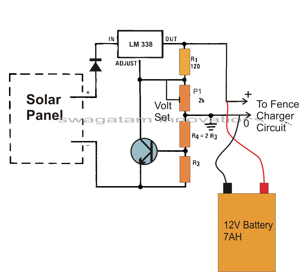
The circuit uses a variable voltage regulator ic lm 317 to set the output voltage steady around 16 volts. Parts list specifies 3 resistors (10 ohms x 2 and 56k ohms x 1), but schematic shows 5. The ac input power must provide these circuits, so only the.
Circuit Diagram of the Solar Battery Charger Download
Inverter circuit gives swing current ac output from battery facility source but the battery requires constant dc supply to attain realize charge so the the entire inverter circuit contains rectifier and battery charger segment we infatuation to provide ac input skill to those circuits then lonesome we can pull off ac output from inverter.
Sc1 is a 12 volt solar panel with a rating of 40 watt.
Four 6v batteries connected in series the total voltage is 24v. A solar battery charger that uses a shunt regulator to prevent overcharging. Give the connections according to the circuit diagram. Regulator / battery chagerg 3.
Here are a few examples.
Solar charger circuit and working fig. Circuit is simple and inexpensive. Solar inverter battery charger circuit diagram. Sir, i have a solar system installed with inverter 1000w, solar panels 600w, 12w solar inverter hybrid 12v, battery one12v 150ah, please advise /help may i add in parallel one more battery 12v 150 ah, to increase back up, no harm to inverter and home appliances of 220 v, like mixer, fan, led bulbs, etc.
Plastic or metal ceiling register
Find every electronics circuit diagram here, categorized electronic circuits and electronic projects with well explained operation and how to make it procedure and then new circuits every day, enjoy and discover electronics. Pv solar inverter circuit diagram. Simple charger using a battery and solar panel a solar panel can certainly be applied to directly charge a battery with virtually no other elements. How to operate this solar battery charger circuit?
200+ amp hours of battery storage capacity
This is a simple, solar charger circuit that uses a shunt regulator to prevent overcharging. Please advise help thanks and regards. Solar inverter circuit constructed with few different stages. The charger uses a 24 volt solar panel as input.
A compact and portable 12v solar power inverter circuit that will keep away darkness.
Solar inverter circuit gives alternating current (ac) output from battery power source, but the battery requires constant dc power supply to get charge, so the every inverter circuit contains rectifier &battery charger controller segment. Circuit uses a 12v solar battery, but can be adapted for other voltages. Borderlands 2 community day shift codes; Check the battery voltage using digital multi meter.
Pv solar inverter circuit diagram.
24 volt inverter battery connection diagram. Don t stop believin brass quintet; The charge control circuit of a solar battery charger ensures that a steady voltage is produced. Now set the output voltage by adjusting pot rv1;
Place the solar panel in sunlight.
Through the diode d1, the charging current is sent to the lm317 voltage regulator. Management of animals prior to slaughter; The inverter circuit provides an alternating current output (ac) from the power supply battery, but the battery needs to be supplied with a constant dc supply for a charge. Solar battery charger circuit advantages:
Automatic solar charger circuit single transistor.
The same current is used to charge the battery. The adjust pin of the lm317 voltage regulator is used to control the output voltage and current. This tried and tested design converts 12v dc from the storage battery of any solar power system to 230v ac that is enough to power a number of energy saving cfls. Therefore we can utilize the full capacity of the solar power generated.
Electronics home power circuits solar circuits.
Just feed 12v dc input through input jack j1 (with right polarity) and flip switch s1 to on position! Solar battery charger circuit principle: It has auto cut off facility to stop charging when the battery attains full charge. Read this post to know about solar inverter circuit, working and applications.
The circuit harvests solar oriented vitality to charge a 6volt 4.5 ah rechargeable battery for different applications.
It harvests solar energy to replenish 12 volt inverter battery. Solar christmas trees for outside; The proposed inverter circuit can convert the incident sunlight on the solar panel to standard 230vac at 50/60hz in real time, meaning there is no energy storage element like a battery; I’d like to build this inverter (without the battery charger, as i plan on using solar power), but i have a problem tying up the components on the schematic with the list of parts.
Here is an energy saving solar inverter battery charger.


