Older homes and buildings may still use fuses instead of circuit breakers which you can use to tell if you have a single. How to determine the motor configuration. Single phase to three phase conversion is also known as phase conversion and that process should be using devise in known as phase convertor that’s convert single phase electric power to three phase or multiple phases.
Three Phase Inverter Circuit Diagram DIY Electronics
Single phase to 3 phase converter wiring diagram wiring diagram is a simplified welcome pictorial representation of an electrical circuit it shows the components of the circuit as simplified shapes and the power.
Single phase igbt inverter circuit diagram loobys author:
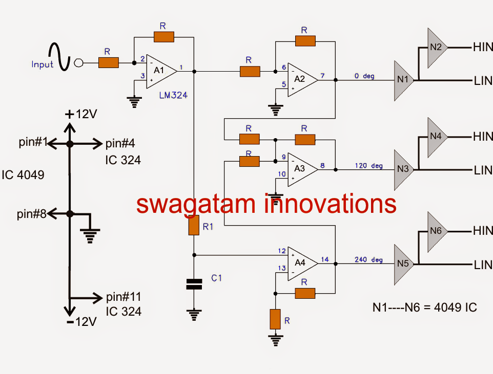
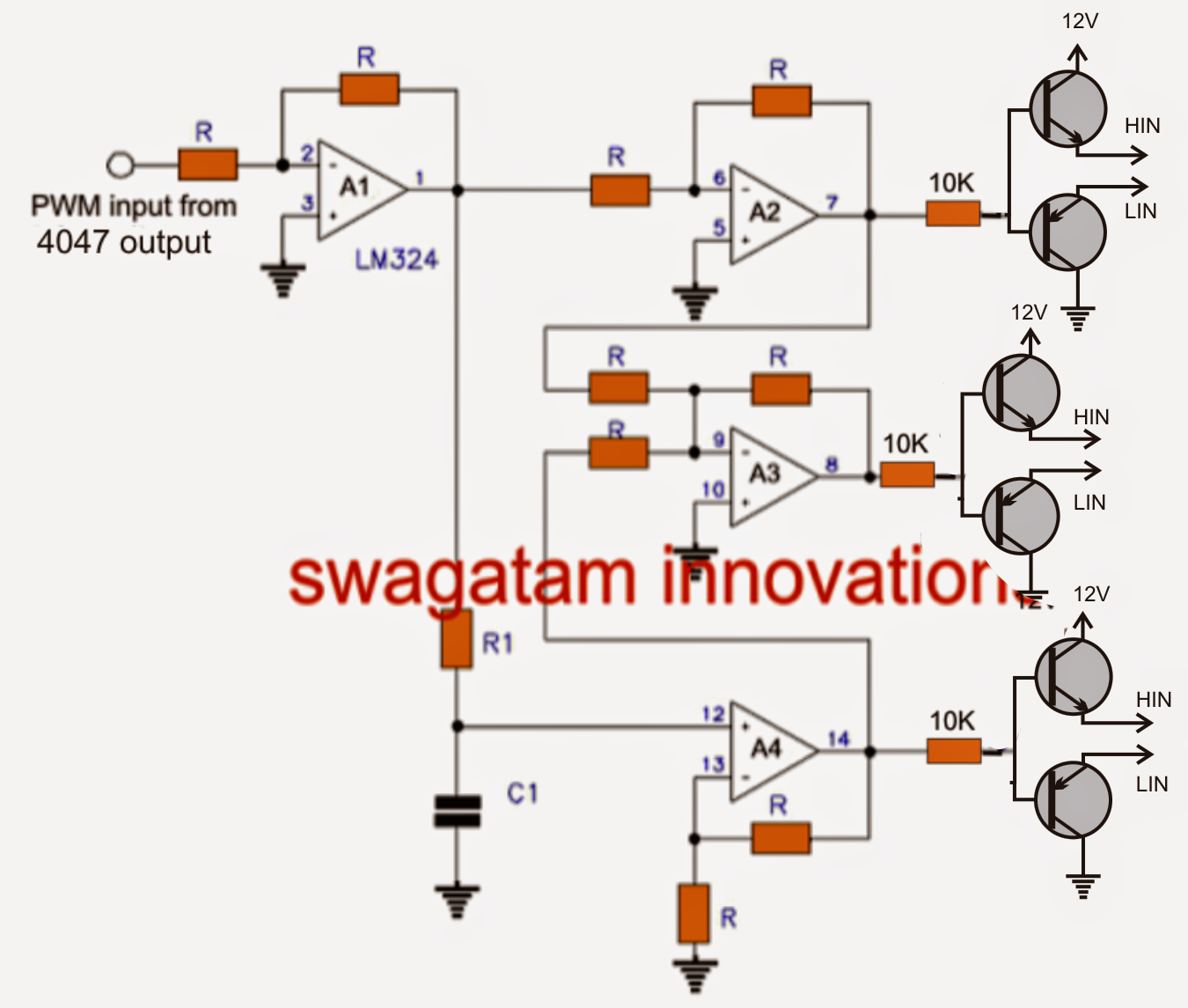
As you can see this six mechanical switch setup is more useful in understanding the 3 phase inverter working than the cumbersome thyristor circuit. We will also take a look at the wave form generated by arduino. The circuit diagram of the power circuit is shown in figure below. Single phase inverter is an electrical circuit, converts a fixed voltage dc to a fixed (or variable) single phase ac voltage with variable frequency.
If we draw the voltage waveforms for each phase then we will have a graph as shown in the figure.
Is there a 4 kw single phase inverter? In this article, we will discuss 3 phase inverter circuit which is. To support my work and donations: Run on a three phase supply from 380v to 415v phase to phase.
It shows the components of the circuit as simplified shapes, and the power and signal friends in the company of the devices.
In this circuitry, the 6 scrs are linked in this sequence scr1, scr6, scr2, scr4 scr3 scr5, and capacitors from c1 to c6 offer the commutation needed through scr. 3 phase forward reverse switch wiring diagram earth bondhon reverse delta connection switch to convert […] The power circuit of single phase unipolar inverter consists of four bidirectional igbt arranged in bridge form. The tools motor performed this function with the static converter, but at the cost of some loss of power.
In the circuit the rotary converter is nothing more than a second motor which is acting as a generator.
3.6 (a) shows single phase bridge inverter with rl load. We will have a brief look at the three phase transformer working and we will construct a three phase transformer using three “single phase transformer” by combining the windings in delta and start connections. 0.75 kw single phase to three phase frequency inverter. In the graph, we can see three voltage waveforms are out of phase with each other by 120º.
A basic 3 phase inverter includes 3 single phase inverter switches where each switch can be connected to one of the 3 load terminals.
As this 3 phase inverter circuit diagram motor controller, it ends in the works mammal one of the favored books 3 phase inverter circuit diagram motor controller collections that we have. The three wires from the inverter go directly to the u, v and w terminals. The construct is same as that of. The circuit diagram of three phase bridge inverter consists of minimum of 6 scr and 6 diodes.
Consider q, q, qb and q as igbts.
The star is sometimes drawn as a three pointed star. The idler motor is under no physical load but it cleans up the signal with the rotary converter. Room air cooler wiring diagram # 2. Single, phase, igbt, inverter, circuit, diagram, loobys created date:
Single phase igbt inverter circuit diagram loobys keywords:
Three phase inverter design/circuit diagram. This capacitor reduces the harmonics feedback to the source. Wiring of the distribution board , single phase, from energy meter to the main. Circuit diagram of three phase bridge inverter:
Here a large capacitor is connected at the input side in parallel with vs to make input dc voltage constant.
This is why you remain in the best website to look the unbelievable book to have. (with capacitor marking and installation) wiring of the distribution board with rcd , single phase, (from energy meter to the main distribution board) fuse board connection. Room air cooler wiring diagram # 1. Three phase inverter ¦ introduction, basic working, circuit diagram.
The drawing shows the star configuration.
Star connection on the right is a typical motor terminal arrangement. 3 phase to single phase rotary converter.