The current flowing through a set is the result of electron tunneling through tunnel junctions of its source and drain. For single phase applications, single phase inverter is used. As microcontroller output is in maximum 5v which is direct to mosfet gate but mosfet is not active until 12v that why we need mosfet driver for our circuit.
mosfet How does this circuit with inverters work
And using a few parts and a small circuit.
It uses an inverter that to me works just like a mosfet gate.
Diodes, capacitors help the circuit to operate smoothly. When use source is 12v battery will have the output of 220v ac 50hz. Simple 12v to 230vac inverter circuit. This simple inverter is constructed around an arduino board which gives very stable frequency of 50hz at 50% duty cycle.
Bc548 / any npn transistor x 2;
Mosfet and scr timer circuit. Top inverter looks like a mosfet with red led at source, bottom inverter looks like mosfet with green led at drain. Regardless, they do not function as inverter at all (inverting logic 0 & 1 ). C1 and p1 adapt the time range.you are able to adjust c1 throughout a range of 100 and 1000 uf to modify the time period range.
Do you want to learn a simple inverter circuit?
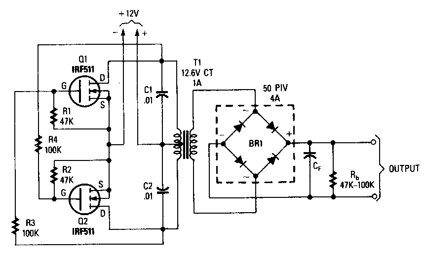
And now whenever ac is needed, dc is again converted into ac to run the ac based appliances. Now you know how a basic inverter works. The next design is a cross coupled simple mosfet inverter circuit will be able to supply 220v/120v ac mains voltage or dc volts (with a rectifier and filter). Single phase half bridge inverter.
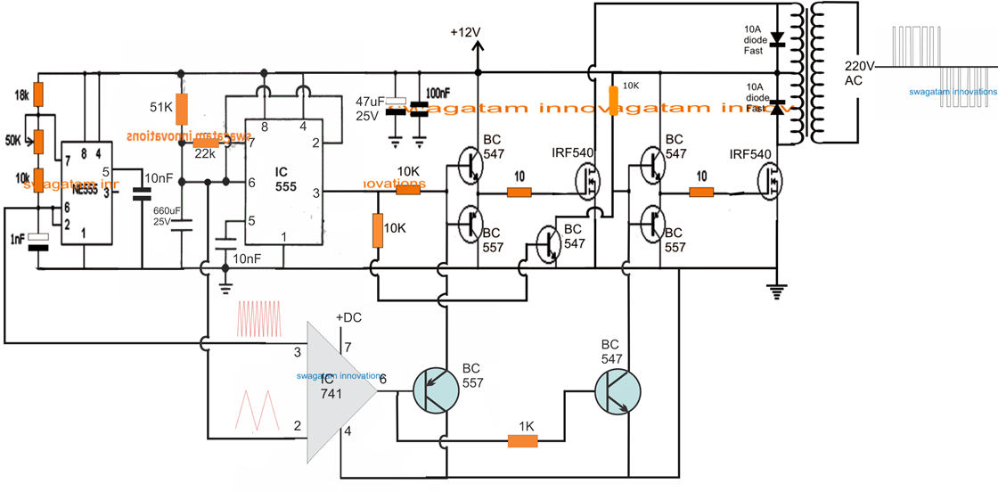
The inverter circuit scheme in figure 3 consists of a series of microcontrollers, mosfet drivers, full bridge circuits, low pass filters and transformers.
Use heat sink with mosfet. Inverter circuits can be very complex so the objective of this method is to present some of the inner workings of inverters without getting lost in some of the fine details. Here we will study how these inverters can be. The construction of this small audio amplifier is very easy and this is very simple.
The arrangement of the inverter consists of four transistor, (mosfet or igbt).to obtain an ac waveform at the output, the transistors are turned on and off in pairs of q 1, q 2 and q 3, q 4.
So the device which converts dc into ac is called inverter. To single pole switches that are energized from a 15v battery. The pwm modulation and circuit operation principle are then Arduino enthusiasts must try this inverter as this is the simplest possible inverter which can be built using a microcontroller board like arduino.
Using a 1 ampere relay you are able to control ac loads as much as 100 watts hooked up to the 1 17 vac or 220 v mains ac.
Here is an ic 555 inverter circuit. For driving the high side mosfet we used tlp250 and a capacitor of 50v, 100µfarad in output of tlp250, this capacitor is called boost strip capacitor. 1 shows half bridge inverter using two transistors (mosfet or igbt). The circuit is an easy to build inverter that will boost 12 or 14 volts to any level depending on the transformer secondary rating.
Here, mosfet is an active load and inverter with active load gives a better performance than the inverter with resistive load.
The diodes are used to protect the igbt from blocking negative voltage. + all static parameters of cmos inverters are superior to those of nmos inverters + cmos is the most widely used digital circuit technology in. Download a better high resolution circuit diagram here. Current flowing through the set is result of the electron tunnelling through the tunnel junctions.
1 shows single phase bridge inverter with resistive load.
Simple inverter circuit using arduino. Simple audio amplifier circuit using single mosfet for mobile. The main advantage of using mosfet as load device is that the silicon area occupied by the transistor is smaller than the area occupied by the resistive load. Half bridge inverter and full bridge inverter.
Single electron transistors (set) substituting mosfets to reduce power consumption of an inverter circuit.
A circuit is used to detect a user degined low logic level and high logic level, by lighting a red & green led. The output is about 50 watts. Because of using 555 timer and mosfet as main. I experiment it to work well.
Total 16 n channel mosfet is used in our project.
Instead of mosfet single electron transistor (set) can be used as a voltage controlled switch. For this purpose, two switching devices are used to convert dc to ac. In this paper, a single phase dc to ac inverter with a low cost driver circuit was developed. This paper represents performance of analysis of low power consumption in single electron transistor (set) for inverter circuit.
The input dc power is.
• complementary mos (cmos) inverter analysis makes use of both nmos and pmos transistors in the same logic gate. Inverter, mosfet, relays, transformer, diode, ic.