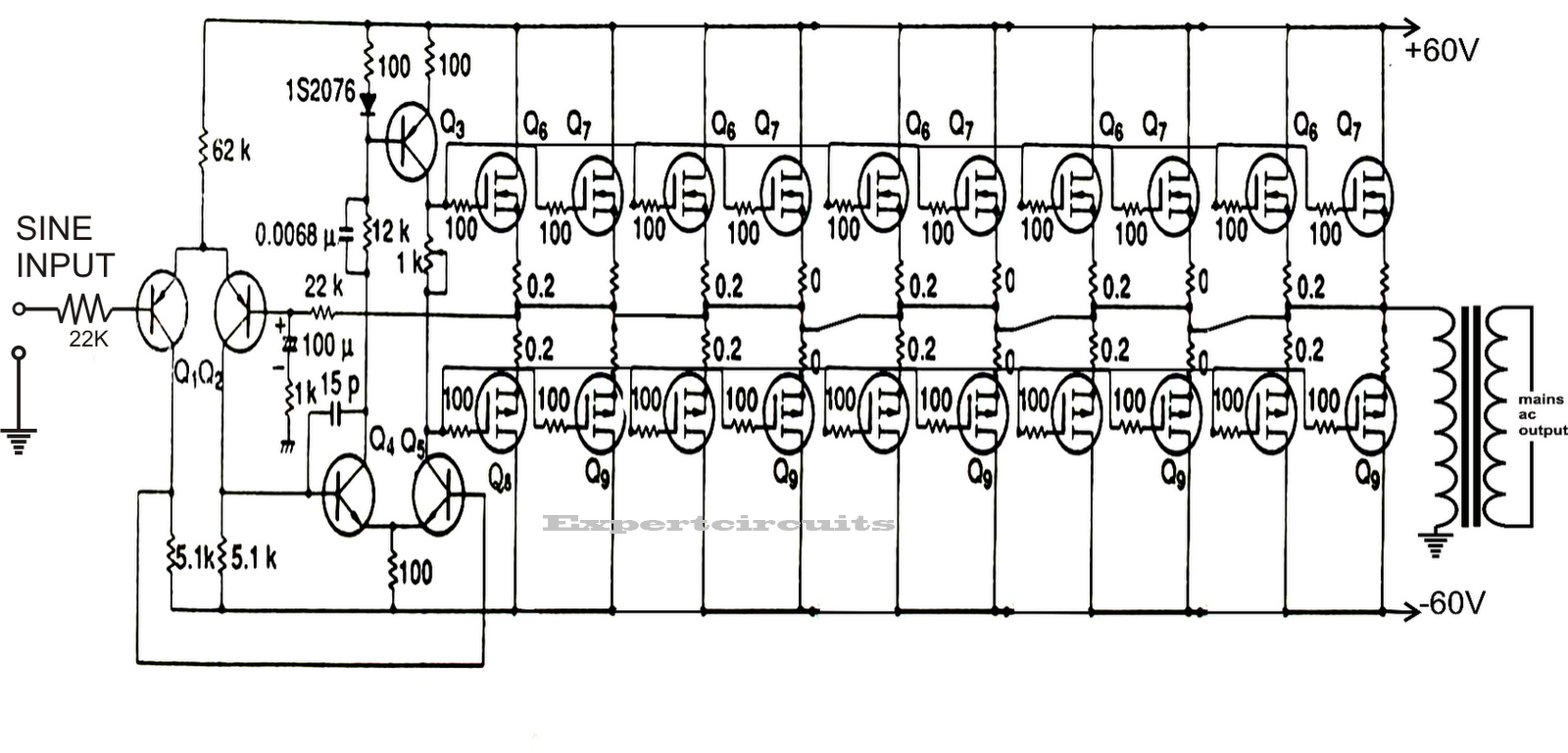
It passes the high dc voltage for specified amounts of time so that the average power and rms voltage are the same as if it were a sine wave. As can be seen in the first diagram below, the configuration is a simple mosfet based designed for amplifying. These pure sine wave inverters are very expensive, where the modified square wave inverters are inexpensive.
Circuits Inverter Pure Sine Wave Circuit Diagram Images
Two types of inverters currently exist on the market;
[thienbaogroup_dau] earlier than finding out the varied designs defined on this article, it could be fascinating to know the components which generally makes a sine wave inverter.
The construction of the sine wave inverter is shown in fig. Wave inverter to a subtle sine wave inverter design. The post details comprehensively regarding how to build a pure sinewave inverter circuit using microcontroller circuit with pic16f72. The basic structure of sine wave inverter is shown on the following diagram.
Few days ago, gohz made a 24v 2000w power inverter in home, sharing some design schematics and circuit diagrams.
Modified sine wave inverter circuit diagram the circuit consists of ic 555 which is tuned to generate frequency at 200hz (square wave) at 50% duty cycle. First with a double voltage module voltage for the op amp power supply. Voltage limits (inverter mode) : An inverter circuit is used to convert dc power to ac power and it can be divided into two types that is pure sine wave inverters or modified square wave inverters.
Pure sine wave inverter project:
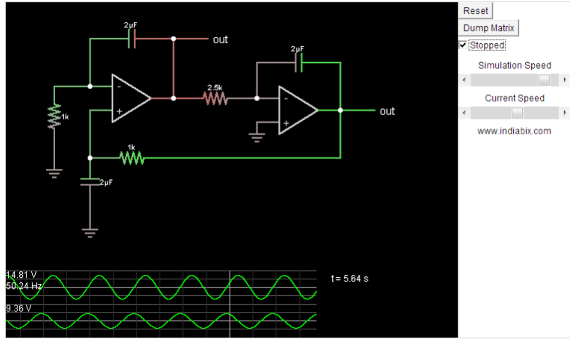
Modified sine wave inverter circuit diagram the circuit consists of ic 555 which is tuned to generate frequency at 200hz (square wave) at 50% duty cycle. It is composed of an. Op amp 1 generates a 50 hz sine wave as the reference signal. A modified sine wave can be seen as more of a square wave than a sine wave;
The inverter shown in the above daigram is a basic square wave design, in order to convert it to sine wave you must follow the steps explained below the mosfet gate/resistor ends must be configured with a bjt stage and the 555 ic pwm should be connected as indicated in the following diagram:
Op amp 2 as an inverter. This is accomplished through an inverter circuit using electronic components. The reference signal is a sine wave. Modified sine wave, and pure sine wave1.
The icl7660 or max1044 can be selected.
The signals used for triggering the switching devices (transistor) are generated by. It comprises a cd4047 multivibrator (ic1), irf250 mosfets (t1 through t8), transistors and a few discrete components. The current of this feature is a continuous positive half of the sine wave. About press copyright contact us creators advertise developers terms privacy policy & safety how youtube works test new features press copyright contact us creators.
Learn more about different types of inverter here.
The put up explains a number of circuit ideas which could be employed for changing or modifying any unusual sq. Make this 1kva (1000 watts) pure sine wave inverter circuit circuit diagram: At this time, output of the power main circuit is a specific harmonic combination, which will obtain the waveform through the filter circuit. Modified sine wave inverter circuit diagram the circuit consists of ic 555 which is tuned to generate frequency at 200hz (square wave) at 50% duty cycle.
This ic is generally used in inverter circuit and we have previously made a square wave generator using this ic, by adding few resistors and capacitors in previous circuit, we can obtain sine wave with ic 4047, as shown in the circuit diagram below:
Sine wave generator using 4047 ic. Sine wave inverter circuit using pic16f72. Sine wave inverter circuit description. Working principle of sine wave inverter.
Circuit diagram of the sine wave inverter.
Sine wave inverter circuit diagram with complete step by step program and coding, in this article i will discuss how to use push pull converter, sinusoidal pulse width modulation, h bridge and low pass lc filter to make pure sine wave inverter circuit diagram. While the carrier waveforms is triangular in nature shown in figure 2. The square wave is fed to ic 4017 which will convert to modified sine wave at 50hz at 50% duty cycle. Make this 1kva (1000 watts) pure sine wave inverter circuit.
275+ 5v higher recovery voltage :
Pure sine wave inverter circuit diagram. The square wave is fed to ic 4017 which will convert to modified sine wave at 50hz at 50% duty cycle. Read free sine wave inverter circuit diagram tube diodes,. A relatively simple 1000 watt pure sine wave inverter circuit is explained here using a signal amplifier and a power transformer.
The following image shows the complete circuit diagram of the sinewave inverter, the images are divided into two in order to fit inside the page, please join them together after.
Modified sine wave inverter circuit. We can also use ic 4047 to generate sine wave. The square wave is fed to ic 4017 which will convert to modified sine wave at 50hz at 50% duty cycle. The function of a sine wave inverter is to convert direct current into alternating current.
Before jumping into the inverter circuit diagram, it is necessary to know the logical symbol of the power inverter.
In this post we are going to construct a modified sine wave inverter circuit using ic 555 and ic 4017. The spwm accuracy of eg8010 was not high enough waveform, so the inverter output was not good enough as pure sine wave. Lower voltage limit :110+ 5v lower recovery voltage :120+ 5v mains a.c. In the electronics or logic design subject, the inverter is also known as the not gate, which does nothing but logical negation.elaborating more, the inverter or not gate makes the high a low and the low a high.
So the output frequency of 50hz+50 hz.
Modified sine wave inverter sometimes also known as modified square wave is an upper segment inverter design, above the simple square wave type. I have already discuss all these topics in following articles.i. Sine wave inverter control technique. We will explore the proposed inverter circuit stage by stage.