The led digital voltmeter working with circuit diagram can be easily understood with this simple overview description below. Multimeter is a measuring instrument. Use a multimeter to determine:
How can the working principle of digital multimeter be
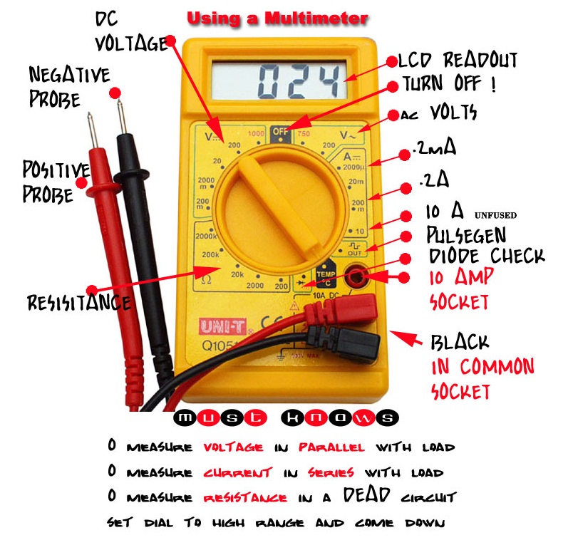
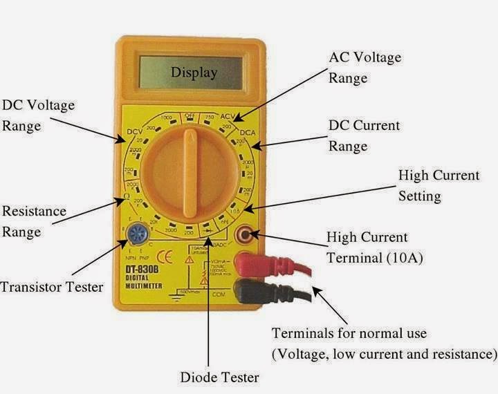
A multimeter, shown in figure 1, is a device used to measure two or more electrical quantities.
It can be used to measure voltage, current and resistance.
An attenuator is used in input stage to select voltage range. An analog meter (figure a) moves a needle along a scale. Simple circuit diagram gone ammeter and voltmeter ammeter and voltmeter circuit diagram current electricity. Next, adjust vr1 until the voltage at pin 36 is equal to 100 mv.
Once this device is connected in series in the circuit, then the total measurand current will flow through the meter.
On an analog multimeter, you’ll have different types of scales. The voltage at their junction is buffered by t1, and then passed to reference diode d1 via r3. It's a simple multimeter capable of accomplishing varied measurements. The calibration of this circuit is done by adjusting r12 (scale/sensitivity) and r14 (zero offset).
There are two main types of multimeters.
S1 is employed as a range switch, and operates in collaboration with s4 (s1/x10) and s3 (x l) or s2 (x3). The following circuit represents the basic circuit diagram and the connection of the ammeter circuit in series and parallel are shown below. Safety glasses, 4aa battery pack, alligator clips, multimeter all exercises require safety glasses over your eyes, all the time! A digital multimeter is one that is capable of measuring voltage, current, of alternating current circuits as well as direct current circuits.
Analog multimeter shown in the figure is cheap but difficult for beginners to read accurately.
This is the 1st part of our lcr tutorial in which we are going to make an inductance meter. Digital multimeter block diagram explanation. A multimeter can be used to measure electrical functions such as voltage, current, resistance, continuity and some are able to measure electrical frequency. Electric circuits like ac lighting circuit, battery charging circuit, energy meter, switch circuit, air conditioning circuit, thermocouple circuit, dc lighting circuit, multimeter circuit, current transformer circuit, single phase motor circuit are explained with diagrams.
0 25 1 minute read.
Voltmeters and ammeters are used to achievement voltage and current respectively here we will discuss both subsequent to ammeter and voltmeter circuit diagram. Then, this value is decoded and displayed on led based electronic display. The circuit has the capacity to calculate voltages right up to 2000 ac/dc v. Internal adc of this ic reads the voltage that to be measured and compare it with an internal reference voltage and converts that into the digital equivalent.
Then only it becomes the digital avo meter.
A transistor is a current controlled device so resistance is inserted in series with the transistor q 1 to select the voltage range. On digital ones, look for similar tags next to a number. Working of this digital voltmeter circuit is very simple. This is a voltmeter circuit that use fet as the buffer to improve the input impedance.
The current flowing through each device in the circuit, and ii.
The voltage intended to measure is primarily converted into digital equivalent using dual slope type analog to digital converter inside the ic7107. These are labeled “ac” or “dc” and have a v for “voltage.” Then, applied power to the circuit. The article points out a straightforward digital panel type voltmeter circuit utilizing a single ic l7107 and a couple of other normal parts.
The calibration of this circuit is done by adjusting r12 (scale.
In addition it must have a provision for measurement of resistance also. Beside that, a cathode follower in a vom of this circuit is the 2n3819. Draw a schematic diagram of the circuit using the appropriate symbols. Circuit diagram and working explanation:
The circuit diagram for a direct coupled amplifier dc voltmeter using cascaded transistors is shown in figure.
Pcb and components layout of simple digital voltmeter circuit. 3 assorted resistors, 4 assorted batteries, 3 assorted leds, 1 spst toggle switch, 1 dpdt knife switch, fuse, motor. How to use a multimeter and build a simple circuit. I'm looking for the internal circuit diagram of dt830x (or dt830d).
The current flowing through each device in the circuit, and
The oscillator is based on an inverter contained in type 74hc14 and generates a. The digital multimeter is the most advanced measuring instrument that makes use of modern integrated circuits for making electrical measurements. The construction of ammeter can be done in two ways like series and shunt. Digital multimeters are widely accepted worldwide as they have better accuracy levels and ranging from simple 3 ½ to 4 ½ digit handheld dmm to very special system dmm.
Capacitance meter using ic 74121.
Beside that, a cathode follower in a vom of this circuit is the 2n3819. This is a voltmeter circuit that use fet as the buffer to improve the input impedance. The simple capacitance meter all described here is able to measure capacitances between 100 pf and 1 pf over five ranges. The potential difference (voltage) over the battery and the light/motor d.
First, you need to determine the characteristics of your meter movement.
On analog multimeters, there’s a scale on the display labeled as ohms, resistance or the ohm symbol (ω). In the upcoming parts of this series, we will upload information and circuit diagrams of the capacitor and resistance meter. To determine this, connect the meter movement, a potentiometer, battery, and digital ammeter in series. Adc inside the ic is integrating converter or dual type analog to digital converter.
Identify on your schematic diagram i.
Make a simple arduino lcr meter (inductor meter) electroveins august 02, 2021. Here are ten simple electric circuits commonly found around the home. This simple capacitance meter circuit provides 14 linearly calibrated capacitance measuring ranges, from 5 pf to 15 uf fsd. Most modern multimeters are digital.
The function of the meter can be changed by switching the dial.