By apichet garaipoom january 8, 2014 52 comments. Op amp 1 generates a 50 hz sine wave as the reference signal. This simple inverter is constructed around an arduino board which gives very stable frequency of 50hz at 50% duty cycle.
Simple Dc to Ac Inverter Make 3 Steps (with Pictures
I have included circuit diagram using igbt, pic18f886 circuit diagram, assembly language program for pic16f886 and hex file in pdf format.
Also note that both ics contain a zener clamp structure between the chip vcc and com, which has a nominal breakdown voltage of 15.6 v.
This is a simple inverter circuit based upon 13007 transistor. The picture was taken in. Now i can see two popular versions: This circuit is very simple because it does not require custom transformers or coils.
Even robot systems occasionally need a negative supply voltage for some purpose or other, and in this kind of application, in particular, there is a need for an effective circuit that does not make greater demands then necessary in terms of current or space.
The 0 ω resistor on pin 1 selects the operating frequency. Simple 100 w inverter circuit 1. This software is used for diagram making. Simple low power inverter circuit | 12v dc to 230v or 110v ac | diagram using cd4047 and irfz44 power mosfet.
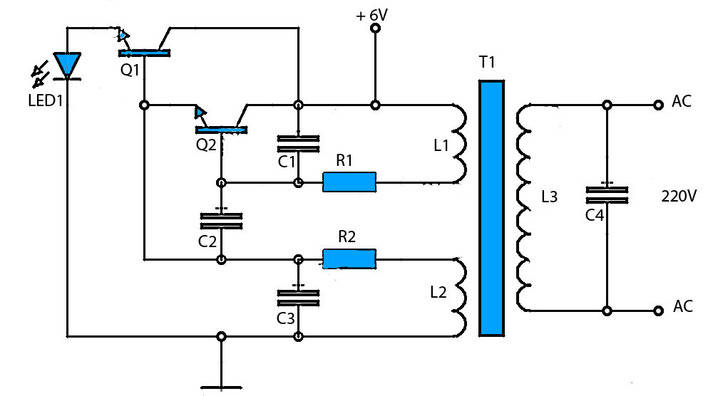
Simple mini power inverter circuit diagram:
The timer ic555 is used as a switching pulse oscillator and it is the main part in this circuit, ic 555 configured as astable multivibrator to give continuous switching pulse, two switching transistors tip41a (npn) and tip42a (pnp) drives. How to make a welding machine with your own hands at home invertor spot from the microwave and others. This simple low power dc to ac inverter ( dc to ac converter) circuit converts 12v dc to 230v or 110v ac. A pure sine wave, after passing it through an lc filter.
Inverter circuits are among the easiest circuits to build for newbies.
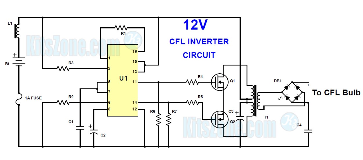
By doing simple modification you can also convert 6v dc to 230v ac or 110v ac. Below is the functional block diagram of the ir2153 series. The circuit is simple low cost and can be even assembled on a veroboard. Use edrawmax for circuit diagram creation.
It contains all the necessary features and libraries that will suffice you in your diagram making.
Also all components are readily available. This is an easy inverter circuit based upon 13007 transistor. Scr1 starts charging the battery. Here the simple mini ups circuit diagram.
Smps welding inverter circuit simplified diagram of primary 25khz using thyristor mini machine for small schematics service selma arc 160 igbt power factor sources a simple made up to 100a tig uc3845 their rukami160a ac machines arc200 electrical.
Here the simple mini ups circuit diagram. This is example of a simple inverter that can be used to power fluorescent lamp and a small strobe. Mini power inverter schematic circuit diagram. Op amp 2 as an inverter.
In ir2153d, a bootstrap diode (d1) is included (it’s a separate dye).
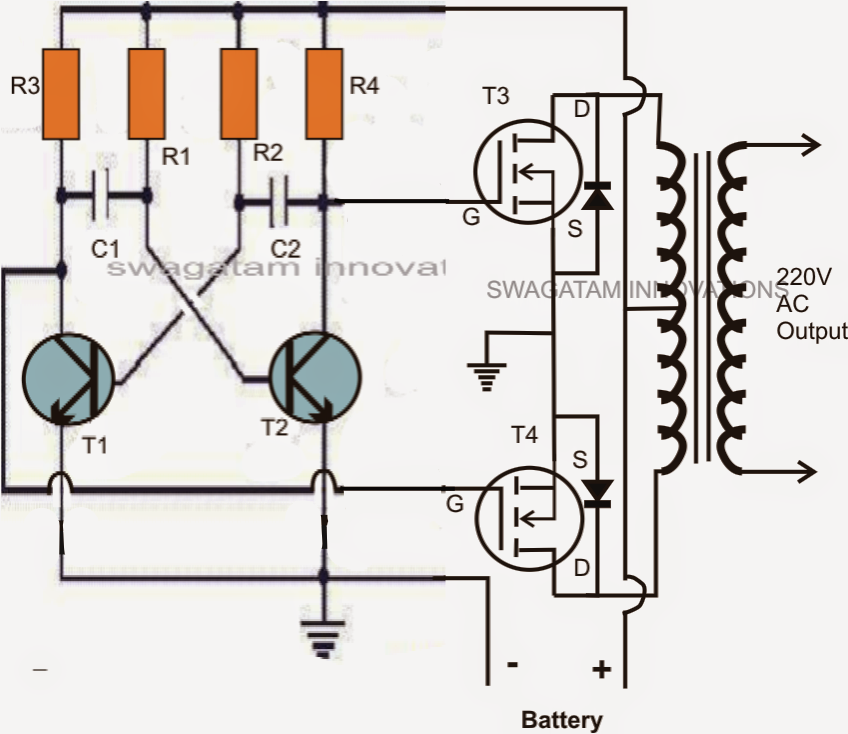
Simple electronics projects for beginners. So, in today’s tutorial, we will take a look into a step by step process on how you can build a simple 12v to 220v inverter circuit using two irfz44 mosfets. This article is a collection of simple electronics circuits we have published over a span of 3 years, which can be used as simple electronics projects for students, beginners, engineering students and other hobbyists.the following circuits listed below can also be used for your mini project needs. Cd 4047 is a low power cmos astable/monostable multivibrator ic.
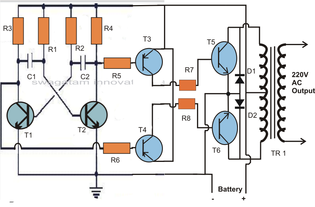
Here is the circuit :
We can create simple small inverter circuit to handle low power devices. Simple inverter circuit using 6 transistors. First with a double voltage module voltage for the op amp power supply. 9/06/2015 · 230v, 50hz, 1.5kva, full bridge pure sine wave inverter circuit using sinusoidal pulse width modulation.
Without it, at 10 khz.
The circuit is simple low cost and can be even assembled on a veroboard. With r1 fitted, the circuit operates at 80 khz; When mains 230v ac is available, ic1 provides the gate voltage to scr1 (tyn616) through diode d3 (1n4007). The backup battery will take up the load with no spikes or delay when the mains electrical power gets interrupted.
This inverter circuit functions on the principle of converting a pure dc signal into a free running square waveform, through the help of a multivibrator circuit operating in astable mode.
This circuit will produce over 400vdc from a 12 vdc, 2.5 a power supply or marine battery or an auto. The icl7660 or max1044 can be selected. There are many basic electrical circuits for the power. This inverter is sweet for little loads like 15w led bulbs, mobile charger, and other electrical accessories.
Charging circuit is built around ic1 ( lm317) as shown below.
You can use edrawmax for making a circuit diagram of an inverter. Simple inverter circuit using arduino. 1 dptof ece,lbrce abstract the circuit diagram of a simple 100 watt inverter using ic cd4047 and mosfet irf540.


