Bc548 / any npn transistor x 2; Inverters (not gates) are available on logic ics but if you only require one inverter it may be better to use this simple transistor circuit. We can create simple small inverter circuit to handle low power devices.
Transistor inverter circuit Basic_Circuit Circuit
This npn transistor is commonly available in market.
The timer ic555 is used as a switching pulse oscillator and it is the main part in this circuit, ic 555 configured as astable multivibrator to give continuous switching pulse, two switching transistors tip41a (npn) and.
When the switch is closed (or on), the led is off. Simple 12v to 230vac inverter circuit. An inverter which uses minimum number of components for converting a 12 v dc to 230 v ac is called a simple inverter. This video shows the testing procedures of a simple inverter circuit.
A not gate using a transistor is very simple to make.
B) transistor 2n3055 with heat shrink. The transistors in the above circuit holds the most significant part in the working of this circuit where it was wired as a multivibrator. As a result, the circuit may require a large number of components to enhance the voltage. C) resistance 68 ohms, 5 watt.
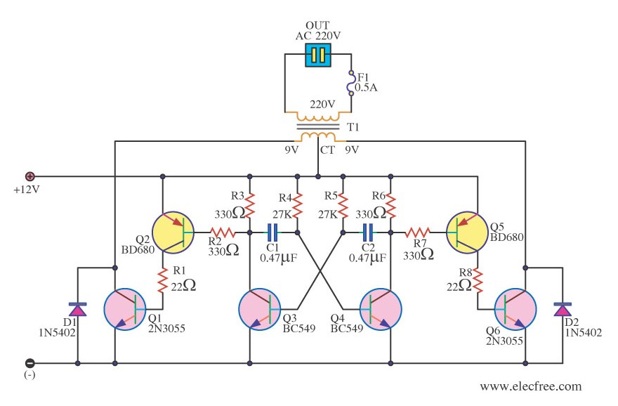
They can convert 12vdc from battery to 220vac or 120vac to apply small light bulbs or lamps max 10 watts.
Download a better high resolution circuit diagram here. These transistors conduct alternately and switch on/off the two lamps. In the two circuit diagram below, just use 2 transistor, 2 resistors, and one transformer only. Here is the circuit diagram of a fully transistorized inverter that can drive up to 60w loads.
In the transistor switch circuit, the.
You'll have exactly the same connections as with the inverter. It is used in inverters and high watt audio amplifier devices. The output from the collector of q2 is connected to the input of the darlington pair formed by q3 and q4.similarly the output of q1 is coupled to the input of the. The simple lamp flasher circuit is created using a couple of fet's, that are put together like a basic astable multivibrator.
It's a simple schematic, but you still have to make a few simple calculations.
I tested the circuit implementation using a bc549c npn transistor, however almost any general. For the entire schematic and construction details, you can visit the following link: This simple inverter is constructed around an arduino board which gives very stable frequency of 50hz at 50% duty cycle. How to make simple inverter circuit diagram within 5 minutes.
3) simple inverter circuit using 4 transistors.
We can achieve 220v ac at the output of just 12 volts. The output signal (voltage) is the inverse of the input signal: Referring to the circuit design below we can see that the inverter circuit uses just 4 transistors, a transformer, and a battery to implement a ful 100 watt power output from a small. This circuit uses a commonly available bipolar junction transistor (bjt).
The above circuit is known as digital inverter since obtained output wave was a square wave.
This circuit is great for education purpose and easy to make. Btw, a pnp is an option, but more often an npn will be used. Our inverter circuit uses one pair of 2n3055 transistor. Transistors q1 and q2 forms a 50hz astable multivibrator.
Arduino enthusiasts must try this inverter as this is the simplest possible inverter which can be built using a microcontroller board like arduino.
A very simple inverter circuit using 4 transistor only is discussed in the following article, which can be quickly built by any novice in the field. A 12 v lead acid battery is the most standard form of battery which is used for operating such inverters. This part of the circuit provides the continuous square wave pulses needed for its working. The inverter circuit presented here is almost identical to the transistor switch circuit with one critical difference.
When the input is high (+vs) the output is low (0v).
The transistor inverter is implemented here using pn2222a npn transistor (a variant of the 2n2222a) but many common npn bipolar junction transistors could be substituted. Simple inverter circuit using arduino. Here, we are using two 2sc1815 transistors, configured as a multivibrator circuit running in astable mode, in order to generate a free running square wave. Let's begin with the most simplest in the list which utilizes a couple of 2n3055 transistors and some resistors.
There are several ways to create an inverter when an engineer needs to convert dc to ac electricity.