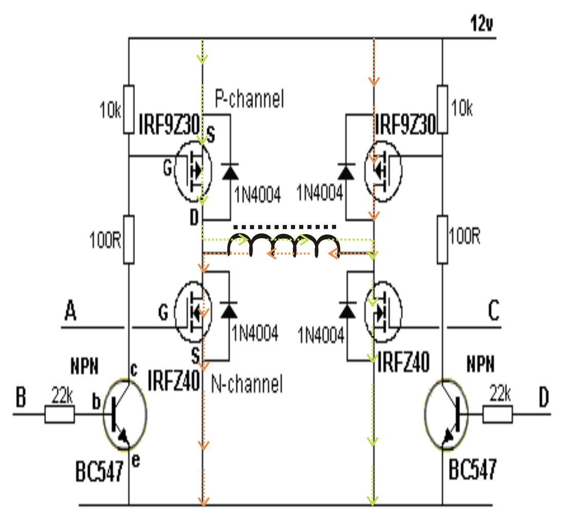
The inverter capable to handle loads up to 1000w, it’s depended on your power inverter transformer. Diagram gt 8145 simple domestic wiring diagrams full version. This is the power inverter circuit based mosfet rfp50n06.
1000W Power Inverter Circuit Design Inverter Circuit and
Make this 1kva (1000 watts) pure sine wave inverter circuit.
A relatively simple 1000 watt pure sine wave inverter circuit is explained here using a signal amplifier and a power transformer.
As can be seen in the first diagram below, the configuration is a simple mosfet based designed for amplifying. It is necessary to connect a fuse with the power line and always a load have to connected while power is being applied. Dc power source / battery bank. Transformerless inverter circuits circuit 1000 watt modified sine wave switching dc ac 12v make your own full homemade 2000w power with 5kva ferrite core 2kva all about simple sinewave self charging off grid pure 1kva diagram solar 5000w 48v pwm based on sg3524 inverters 500w to 220v tied if a higher.
Inverter circuits are among the easiest circuits to build for newbies.
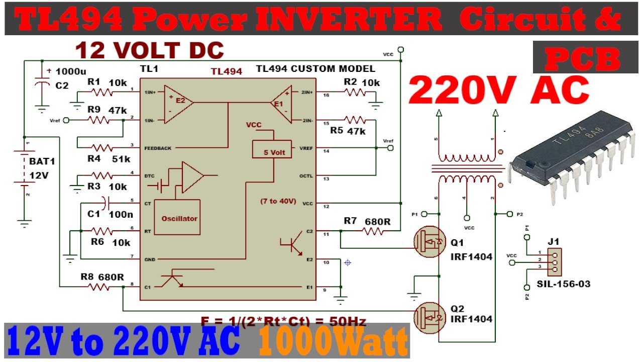
The diy inverter board can handle up to 1kw (depending the transfor… Can someone sent me a 1000w 12v dc to 220v ac circuit diagram with a frequency of 50hz, the circuit diagram should be practical so that i can try it in the laboratory. Now the simplified inverter stages are: This is an easy inverter circuit based upon 13007 transistor.
Heatsink is required for cooling the mosfets.
Heatsink is required for cooling the mosfets. Luminous inverter battery connection diagram. This power inverter is designed for 12v dc, but also can be connected to 24v dc, my goal is 800 watt, strive to 1000 watt pure sine wave output. 555 is a timer ic which is used to generate time delay.
The inverter capable to handle loads up to 1000w, it’s depended on your power inverter transformer.
The rfp50n06 fets are rated at 50 amps and 60 volts. The project is based on the low cost egs002 spwm driver board module. The rfp50n06 fets are rated at 50 amps and 60 volts. The inverter is a transformer base and not chopper or circuit base inverter and the transformer winding is a home made transformer winding formula which i have been using for any inverter winding, if i should start explainning how i wind the transformer it will take a longer time but if you have enough time to experiment this simple.
Last updated on august 3, 2020 by swagatam 241 comments.
This simple inverter is constructed around an arduino board which gives very stable frequency of 50hz at 50% duty cycle. This is the power inverter circuit based mosfet rfp50n06. China 1000w power inverter dc 12v to ac 220v circuit diagram solar. The circuit is simple low cost and can be even assembled on a veroboard.
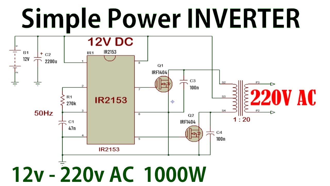
Learn how to build this cheap mini inverter and power small 220v or 120v appliances such drill machines, led lamps, cfl lamps, hair dryer, mobile chargers, etc through a 12v 7 ah battery.
Buy luminous solar cruze 3 5 kva inverter charge controller shine 4850 konark energy regalia is solar ready inverter and can be connected to both the grid and solar. How to make simple inverter & diagram simple inverter | gonou hello all of you , here i just want to share some idea that can make you all save money at home with method ( about led light bulb ) by just make simple inverter using transistor d718 pnp x2 , resistance 1k ohm 0.2w x2 & transformer 12v 3a & battery 12v dc. This inverter is sweet for little loads like 15w led bulbs, mobile charger, and other electrical accessories. The inverter capable to handle loads up to 1000w, it’s depended on your power inverter transformer.
Diy cheap 1000w pure sine wave inverter (12v to 110v/220v):
The rfp50n06 fets are rated at 50 amps and 60 volts. Simple 1000w power inverter circuit diagram. These 7 inverter circuits may look simple with their designs, but are able to produce a reasonably high power output and an efficiency of around 75%. Simple inverter circuit using arduino.
This inverter is designed to power about 2200 watt, the headline of this paper is 2000 watt is because the dc power supply maximum output current is 100a, so gohz tested it at 2000 watt, for more than 12 hours testing, it can work well at 2000 watt, there.
The home inverter overall structure is, downside is a large cooling plate, upside is a power board with same size as the cooling plate, length 228mm, width. We have so many collections wire wiring diagrams and schematics, possibly including what is you need, such as a discussion of the inverter circuit diagram. China inverter circuit diagram 1000w luminous inverter inverters. Diagram 1000w power inverter circuit diagram:
1000w 12v dc home power inverter circuit board design.
1000w power inverter circuit diagram: Car batteries for powering you home? This 1000 watt power inverter circuit diagram based on mosfet rf50n06.if you want more power then add additional mosfet paralleled at rf50n06.this mosfets are 60 volts and 50 amps as rated. This power inverter has a good starting ability, it only takes about 1 second for two parallel 1000 watt solar lamps.
This is the power inverter circuit based mosfet rfp50n06.
12v dc to 220v ac inverter circuit pcb basic schematic for diagram the 2 wind power 100w switching transformerless simplified 240v electronic supply 5w solar 60w 230v voltage converter transformer less grid tie page 3 china 1000w simple 120v pure sine wave how build a projects. The circuit built based ic cd4047 to generate sine wave signal 50hz and then the power transistor 2n3055 will boost the signal so that the signal have high power high electric current.