About 10 4v projects circuits emergency light circuit diagram fluorescent lamp electronic ballast cfl lamps dc to dc inverter circuit electronic ballast for fluorescent lamp simple high voltage inverter with input supply voltage ranging 3v to 6v dc cheap emergency light circuit diagram using a flas me a suggestion if i only want to, an1543 d. C1 = 0.01uf, c3 = 0.1uf; The purpose is to reduce the inverter transformer size and weight, output is square wave.
3 Ic Cfl Inverter Circuit Circuit Diagram Images
The circuit is simple low cost and can be even assembled on a veroboard.
The circuit is designed by t.kalpana.
R1 = 220k pot, needs to be set for acquiring the desired frequency output. The basic construction of a cfl consists of a fluorescent glass tube and a compact electronic ballast in the base of the lamp. This inverter built using transistors for both the square wave generator module and the amplifier module. This is a small inveter circuit.
It is possible to adjust the frequency of the square waveguide with the pot.
This circuit is envisaged frequency in 300hz. This simple low power dc to ac inverter ( dc to ac converter) circuit converts 12v dc to 230v or 110v ac. This inverter is sweet for little loads like 15w led bulbs, mobile charger, and other electrical accessories. The circuit is designed by t.kalpana.
The cooling transistor connected to the output of 555 causes constant currents to pass from the transformer.
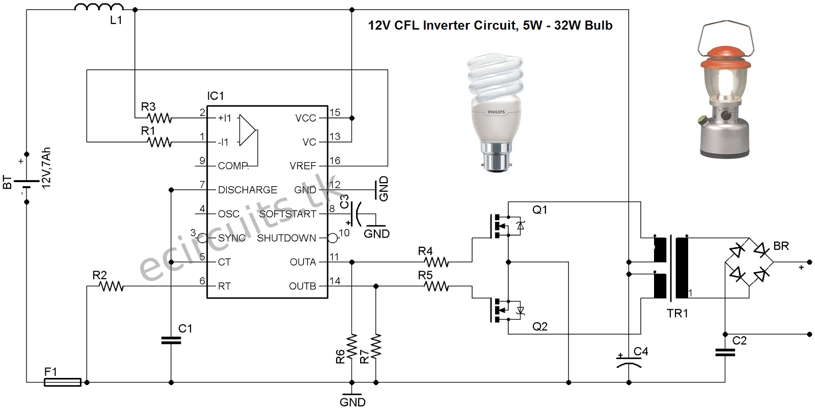
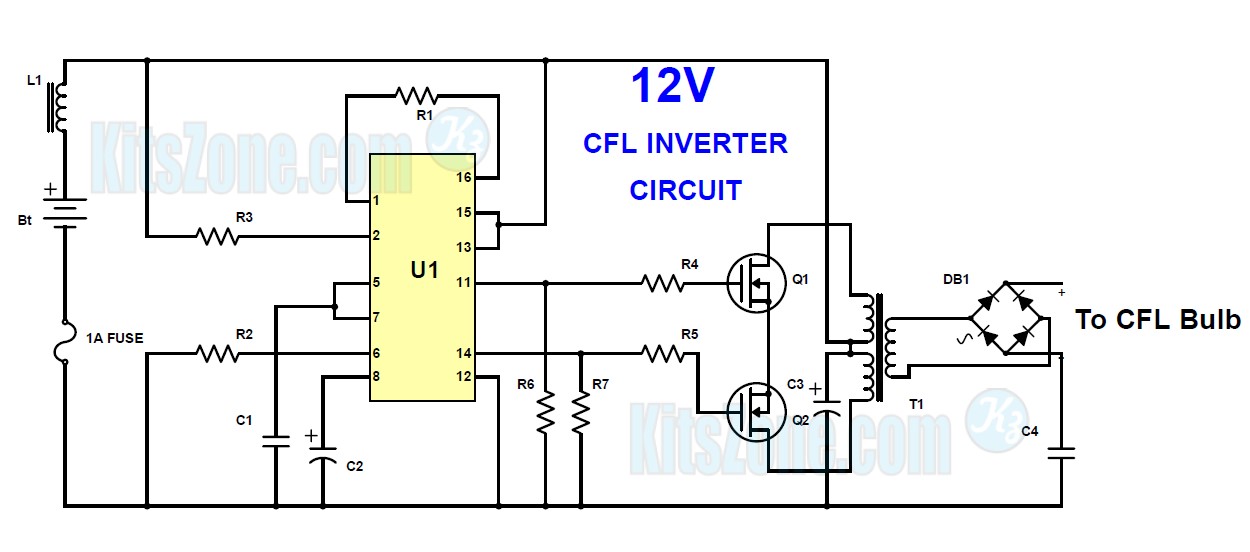
Leave a comment / uncategorized, inverter circuit / by admin. Inverter circuit is typically used for emergency lighting, since the power output is small, which is about 5w only. This circuit will produce over 400vdc from a 12 vdc, 2.5 a power supply or marine battery or an auto. Simple cfl inverter circuit diagram.
This time we used the larger power transistor 2n3055, and only two resistors are used, and the power of the resistor is selected to be larger, so the output power of the circuit will be corresponding.
This is example of a simple inverter that can be used to power fluorescent lamp and a small strobe. This is an inverter that can drive any 8 to 25watt compact fluorescent tube with a 11to 15v input.it consists of a ferrite core,tip3055 transistor,two resistors,two capacitors. 12v cfl inverter circuit simple diagram draw your wiring 3 ups 50w 12vdc to 220vac electronic schematic index 12 seekic com 50 va card transformer based at rs 250 piece id 4912434648 4 uninterruptible power supply circuits explored homemade projects how make an 40 watts rashri multicolor mother board pcb of 45 watt for wi fi mobile charger dc fan hobby kit. The picture above is our inverter schematic.
This is an easy inverter circuit based upon 13007 transistor.
Current passed through primary winding inducts a magnetic field to the core and the core gives the energy back to the feedback winding with a delay determined by. And technology news 6v dc 20 watt florescent driver eetimes lamps work dim them phrases tattoos for girls bulbs 12v inverter simple analysis of the electronic circuits w works does a convert 220v ac without transformer quora converting dead into an led light homemade projects. Simple 12v compact fluorescent tube ballast/inverter only eight components! Simple inverter circuit diagram pdf.
Here’s a very simple circuit inverter that converts dc current into ac current, from 12v dc to 220v ac with output power of 5w max.
Use a 12v battery to directly run the fluorescent bulb. But you can use this inverter for other purposes that do not require large electric power such as mobile phone charger, small. This can be used as the emergency cfl lighting, cfl needs ac input for operating and this circuit provides the ac to cfl. Simple low power inverter circuit | 12v dc to 230v or 110v ac | diagram using cd4047 and irfz44 power mosfet.
Arduino enthusiasts must try this inverter as this is the simplest possible inverter which can be built using a microcontroller board like arduino.
R2, r3, r4, r5 = 1k, t1, t2 = irf540; Cfl light circuit diagram wiring diagram line wiring diagram. Running fluorescent lamp 12v battery, chay bong đèn fluorescent lamp. Simple and practical 150w power inverter circuit.
Here is the circuit :
Parts list for the above explained 150 watt inverter circuit diagram: Fluorescent lamp is used in inverter circuitry in fluorescent lamps (flashlight). This circuit will produce over 400vdc from a 12 vdc, 2.5 a power supply or marine battery or an auto. By doing simple modification you can also convert 6v dc to 230v ac or 110v ac.
Inverter circuits are among the easiest circuits to build for newbies.
Circuit diagram of a simple inverter, do it urself by femiolorun(m): At the end of that lifetime the bulb will blow out. This simple inverter is constructed around an arduino board which gives very stable frequency of 50hz at 50% duty cycle. This circuit is very simple because it does not require custom transformers or coils.
Automatic light circuit diagram download powerful amplifier circuit diagram ht2884 tv high gain antenna schematic tda7294 ampli.
Fluorescent lamp is used in portable lighting devices with fluorescent lamps (searchlight) in inverter circuit. The following diagram is an inverter circuit which will give you 220v ac 50hz with maximum power output of 100w. A square wave is formed at the end 3 of the 555 integrator used in the circuit. 100w inverter 12vdc to 220vac.
Also all components are readily available.
12v cfl inverter circuit for emergency light this is a small power inverter circuit that produces 230v ac at the output through the transformer. A square wave is formed at the 3rd end of the 555 integral used in the circuit. Fluorescent lamp inverter converter schematic circuit diagram. This circuit is very useful for home, shop, small place for emergency cfl light.
This is a kind of excellent performance power inverter for home circuit diagram, materials are easy to get, and the output power can reach 150w.
In the circuit diagram we can observe that 12v battery is connecter to the diode led and also connected to the pin8 of the ic 4047 which is vcc or power supply pin and also to pin 4 and 5 which are astable and complement astable of the ic. 12v cfl inverter circuit for emergency light. Simple fluorescent lamp inverter circuit diagram this is a single transistor oscillator circuit. It is possible to adjust the frequency of the square wave by the pot.
This is example of a simple inverter that can be used to power fluorescent lamp and a small strobe.
The q1 and q2 used generate square wave. This is a small power inverter circuit that produces 230v ac at the output through the transformer.