12v to 220v using ferrite e42 core + egs002 powerful 600w true sine inverter simple sinewave inverter circuit with waveform 200w modified sine wave inverter ir2110 sine wave inverter circuit in h bridge used in pure sine wave inverter design 2 mosfet are used as high side mosfet and 2 mosfet is used as low side mosfet. Sine wave inverter circuit using pic16f72 pure sinewave inverter using pic16f72 without center tap transformer and without hv transformer: 3.3 the analysis of shift circuit the sg3525 chip oscillates to produce a sawtooth wave and the apex of the sawtooth wave is about 3.3v and the lowest point is about 0.9v.
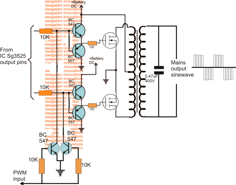
SG3525 Pure Sinewave Inverter Circuit
All in all, says this is a 24v pure sine wave inverter, this power inverter is composed of three parts:
You can use these 24v pure sine wave power inverter circuit diagram in your homes, hotels, offices, or any other commercial properties where power requirement is costly and crucial.
By using the principle of dc to ac conversion (dac), such an inverter system helps to prevent the problem of power failure in homes, offices, etc. Circuit diagram of solar inverter : The post explains a 3 powerful yet simple sine wave 12v inverter circuits using a single ic sg 3525. I also posted a separte articles on pulse width modulation ic or pwm controller ic.
When this part of the circuit access 12v power supply, sg3525 was electric, and then set up by the internal oscillator and external oscillator capacitor c11 and resistors r6.
The output sine wave frequency of this circuit is 50 hz, which is within the required range, so it is feasible to select the rc sine wave oscillating circuit. Here we are mainly using the internal oscillator of pwm sg3525. 3 high power sg3525 pure sinewave inverter circuits homemade circuit projects. Sg3525 inverter circuit diagram and sg3525 pinout.
Using the sg3525 pwm controller explanation and example circuit diagram schematic of push pull converter.
3 high power sg3525 pure sinewave inverter circuits. This is an sg3525 based inverter schematic. I have explained all the main components and their working below. Design of single phase sine wave spwm inverter power supply based on sg3525.
Then i want to use a microcontroller to make a pwm to make a sine @ 230vac 50hz.
Utilizing pwm and analog components, the utilizing pwm and analog components, the output will be a clean sinusoid, with very little switching noise, combined with the inexpensive the microcare pure sine wave inverters deliver true clean sine wave output […] This is a powerful inverter. And we will build the 12v to 230v inverter circuit using pwm ic sg3525. About press copyright contact us creators advertise developers terms privacy policy & safety how youtube works test new features press copyright contact us creators.
12v to 220v dc ac converter inverter circuit diagram with pcb.
Pin on bureau elect1 the following image shows an example inverter circuit using the ic sg3525 you can observe that the […] 25va and later on 80va. The first circuit is equipped with a low battery detection and […] 500va pure sine wave inverter 12v to 220v with anti reverse connection protection circuit 1200va pure sine wave inverter 12v to 220v using ferrite e42 core + egs002 powerful 600w true sine inverter simple.
Finally the most reliable and awaited pure sine wave inverter,it's here for all members.(don't hesitate to contact me @ hisham2630@gmail.com.features:inverter o/p volt :
This article is all about sg3525 inverter circuit and sg3525 pinout and its ic number. It passes the high dc voltage for specified amounts of time so that the average power and rms voltage are the same as if. Sg3525 inverter circuit which can be configured with the the above discussed full bridge network. It has a power 500w, using 4 mosfet irf1404 (202a.
Keep reading if you want to know about inverter circuit using sg3525 ic.
Circuit diagram of solar inverter using sg3525 is given below. Pure sine wave inverter circuit diagram pdf efficient, inexpensive inverter with a pure sine wave output.


