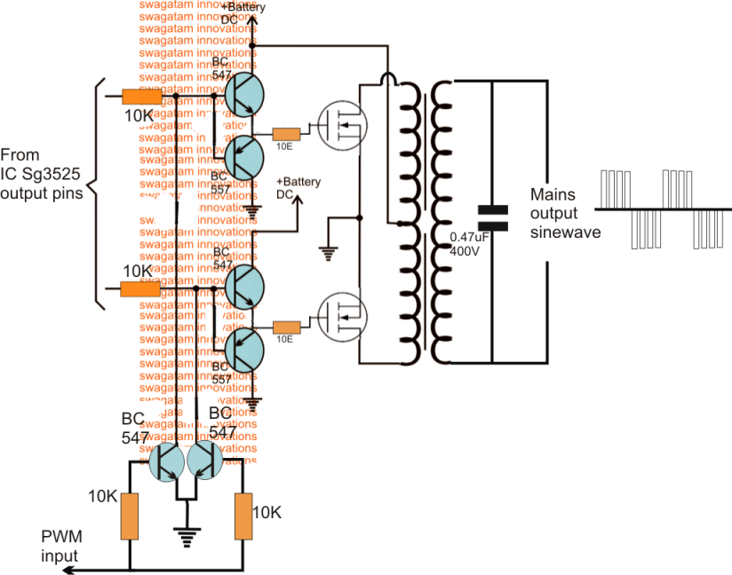
12v to 220v dc ac converter inverter circuit diagram with pcb. 2x60volt smps circuit sg3525 etd44 ir2110 schematic circuit diagram. Inverter circuits are too many.
Sg3525 Inverter Circuit Diagram Componentes
Here we are mainly using the internal oscillator of pwm sg3525.
This is an sg3525 based inverter schematic.
I have included circuit diagram using igbt, pic18f886 circuit diagram, assembly language program for pic16f886 and hex file in pdf format. We use 2 transistor and 2 resistors only. Sg3525 inverter circuit diagram pdf. Design of single phase sine wave spwm inverter power supply based on sg3525.
Hi, in today's video i'll show you how to make a regulated power inverter with the popular sg3525 or uc3525 pwm ic.
Circuit diagram of solar inverter using sg3525 is given below. Now i think it’s time to introduce an inverted that has one of the best inverter efficiency. 3 high power sg3525 pure sinewave inverter circuits homemade circuit projects. Circuit diagram of solar inverter :
I have explained all the main components and their working below.
3 easy sg3525 inverter circuits explored. I have tested the sg3525a on a bread board. A 250w pwm inverter circuit built around ic sg3524 is shown here. Ka3525a smps controller www.fairchildsemi.com fe
Inverter circuit diagram using sg3525.
Home decorating style 2022 for inverter circuit diagram using sg3525 and mosfet, you can see inverter circuit diagram using sg3525 and mosfet and more pictures for home interior designing 2022 317357 at resume example ideas. Using the sg3525 pwm controller explanation and example circuit diagram schematic of push pull converter. And we will build the 12v to 230v inverter circuit using pwm ic sg3525. In this post we learn how to build 3 unique power inverter circuits using the ic sg3525.
All these inverters will produce 220 v or 110 v ac from any 12 v automobile lead acid battery.
9/06/2015 · 230v, 50hz, 1.5kva, full bridge pure sine wave inverter circuit using sinusoidal pulse width modulation. A pure sine wave, after passing it through an lc filter. On camping grounds, automobile repairs in the heart of nowhere, and picnics or party gatherings in the woods, the. The output can be smoothly adjusted from.
Smps circuit sg3525 and ir2110 ics drive mosfets in the installation primer on irpf450 the transformer etd44 feedback 4n33 provided with opto kublin output voltage 2 × 60 volt symmetrical ideal addition to the outlet for supplying amp are approximately 450w power.
The built in circuitries inside the sg3524 include pulse width modulator, oscillator. The basic circuit diagram of the pic controlled single phase inverter draw using matlabsimulink is shown in figure 3. Pls sir i was asked to construct a pure sine wave inverter(not modified sine wave) using sg3525 and 555 ic or 4047 ic as my final year project to be passed on march 24th pls can u help me with a circuit diagram and also if you have any schematic of a pure sine wave (not modified)inverter not modified sine wave you can also send me the link but. Sg3525 12volt 220volt converter with irfz44 and ei33 schematic circuit diagram.
I also posted a separte articles on pulse width modulation ic or pwm controller ic.


