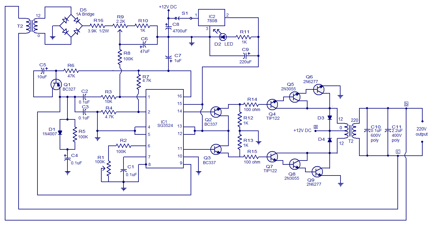
The ic sg3524 gives fixed frequency pwm that can be varied by rt and ct element values. But performs well with other appliances like pc, lightings. 1kva prefered, else any wattage.
SG3524 IR2110 4X MOSFET DIAGRAMS CIRCUIT SHEMS
Hey guys, i've been searching for the circuit of an inverter using sg3524 for about a month.
It is now obvious that i need a sinewave form.
The sg3524 incorporates on a single monolithic chip all the function required for the construction of regulating power suppies inverters or switching regulators. I just want a circuit of an inverter that is. They can also be used as the. I have been using it for 2yrs+.
It is a 16 pin integrated circuit.
Even top inverters manufacture companies also use sg3525 in dc to dc converter part of the inverter. The sg3524 ic integrated circuit has all the functions necessary for the production of a regulating power. 3) inverter circuit using ic sg3524. The inverter has a feedback circuit, that is using the small 220v/12vac transformer t1 (and also the diode bridge and the rest of the resistors till pin1 of the sg3524).
Sg3525 is a voltage mode pwm controller integrated circuit.
Here is a simple pwm dc to ac voltage inverter circuit based on ic sg 3524. A 250w pwm inverter circuit built around ic sg3524 is shown here. Infact it has problem with inductive loads. Hello abubakar, yes the concept can be easily implemented with sg3524 based circuit also, in fact with any squarewave inverter….you can use a 4047 inverter, tl494 inverter 4017 inverter etc….the pwm/bjt stage explained above is a universal sinewave generator design
From the r1 you may adjust the duty cycle (and in this way, the conduction of the power transistors) in respect to the voltage from the secondary of the t2 power transformer.
This 3rd design is easy to build, the output power of 150w, the present simple inverter circuit using ic sg 3524 design frequency of about 300hz, the purpose is to reduce the volume of the inverter transformer, the weight, the output waveform is a square wave. This inverter circuit contains three stages, pwm switching pulse generator; Pwm inverter circuit ic based on sg3524 diagram using 500 watt low 250w 5000w dc ac with feedback control sg3525 pure sinewave circuits regulating pulse width modulator shows the complete circuit diagram of pwm inverter. It is used in maximum inverters available in the market.
It has two pwm outputs both are an inversion of each.
I am responding to your quest for circuit design using sg3524n for inverter.sg3524n is a pwm ic design circuitry that can be use in most electronic design such as inverters,regulated power supply and so on.when use for inverter, it gives a purer modified square wave pwm which is a good approximation of sine wave. The pwm switching pulse generator is the main part of this circuit, which is responsible to produce pwm pulse according to the sine wave reference. Sg3524 drive mosfet i built a square wave inverter with feedback and pulse width modulation using sg3524.


