The other pole of switch s1 is connected to the lamp and the other pole of. Pdf technical manual contains information on maintenance, repair service manuals, specifications, schematics and pictures for round balers john deere.baler parts from john deere. Small 7 pin round (qld)
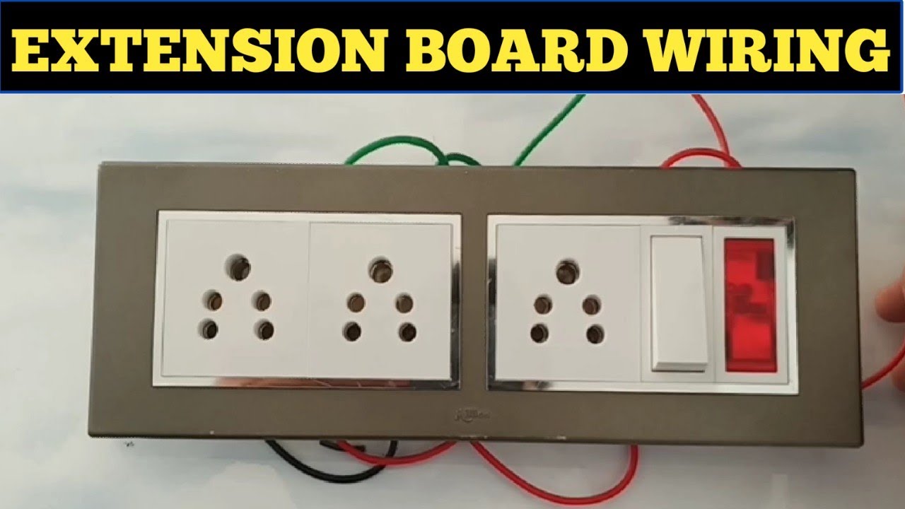
Extension Board Wiring Electric Extension Board At Home
How to wire up a switchboard.
7 pin flat the best!
All diagrams are as viewed from the cable side. Click on the image below to enlarge it. Long extension cords especially outdoor ones can be costly and though they should. In the below wiring diagram, the phase line is connected parallel to the light switch and the plug socket switch.
7 pin trailer plug heavy duty round pole wiring connector 12v towbar towing caravan truck n type end way rv diagram for tandem axle with brakes leisure cords 7 way trailer extension cord wire 12 ft 7 pin connector plug for rv trailer caravan 5th wheel to truck or van heavy duty weatherproof 12 feet 4 7 out of 5 stars 49 29 99 29.
With the right connection, the running lights, brake lights and turn signals will all work properly. John deere round balers manual john deere baler parts diagram wiring diagrams u operation. Here are two wiring diagrams for the 7 pin ‘n’ type trailer electrical plug. The 7 pin flat plug will fit into a 12 pin flat socket and work perfectly.
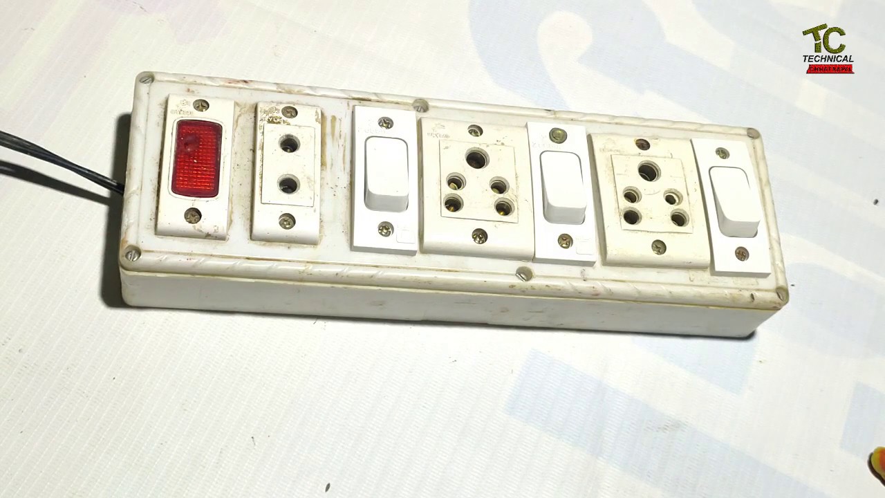
It is really very useful electric board.
It shows current voltage as well as ampere being consumed at the real time. The color coding you see on the motherboard diagram is used to match up ram for dual channel. I was reading 120v between the grounds of the two different outlets. For example the following pictorial diagram shows a two section switchboard.
To wire the iec jack cut off the receptacle side of your 3 or 6 extension cord and then separate the two wires now its time to hook up your electronics following.
And each of the sockets is independently controllable via separate switches. Leisure cords 7 way trailer extension cord wire 12 ft 7 pin connector plug for rv trailer caravan 5th wheel to truck or van heavy duty weatherproof 12 feet 4 7 out of 5 stars 35 29 99 29 99 free shipping by amazon. It is a lengthy flexible electrical cable with a plug at one end and multiple sockets on the other end. Australian trailer plug and socket wiring diagrams.
7 pin trailer connector extension.
In the diagram is shown the method of wiring distribution mainboard form utility pole to energy meter and then dp circuit breaker and sp mcb breaker. Electrical , electrical connection , wirig diagram. All diagrams are as viewed from the cable side. Below is the given wiring diagram of single phase distribution board with rcd in both nec and iec electrical wiring color codes.
12 pin flat this is an extension of the 7 pin flat.
Grey= phase 1 or line1, black= line 2, brown= line 3, blue = neutral and green= earth conductor. Diy electric extension board wiring: 7 pin trailer connector extension. In this instructable i will tell you whole process of making this homemade electric extension board step by step.
Here, one pole of the both spst (single pole single throw) switches s1 & s2 are connected to the phase line of the supply.
An extension cord also called an extension lead or power extender is a power supply expanding box. Switch board circuit diagram.wiring diagram of single phase distribution board with rcd in nec us iec uk eu electrical wiring color codes double pole mcb dp the isolator or main switch this is the main operating switch which is used to control the electric power supply in the building s. The same description and detailes can be used as mentioned for the above fig 1. Vehicle plastic way round electrinic connector towing car rv or other commercial end online in turkey b07j3b8lzz 12s on extension lead convertor twin 7 n s type to euro trailers ltd lights with 6 it easier than you think etrailer guides 4 international standard kea load.
The first diagram is a simple set up of two brake lights, two indicators and two side lights.
7 pin trailer connector extension. This is the main power connection for the motherboard and comes from the power. Caravan wiring diagram car plug wiring diagram line wiring diagram. The electrical socket is a female connector that caries the power source or power supply and transfer the electrical energy when an electrical plug is connected to it.
Generally, the power source is connected to the power socket or electrical.
This special harness is used with most utility and boat trailers. Electrical sockets are used in switchboards, outlets, extension boards, etc. This neat little device solves three problems that i usually come across when experimenting or.