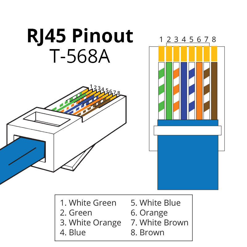
The jack should either come with a wiring diagram or The other two pairs, brown and blue, are unused. On the left is pin 1.
Easy RJ45 Wiring (with RJ45 pinout diagram, steps and
A rj45 connector is a modular 8 position, 8 pin connector used for terminating cat5e or cat6 twisted pair cable.
Ⅵ wiring pinouts of rj45 connectors.
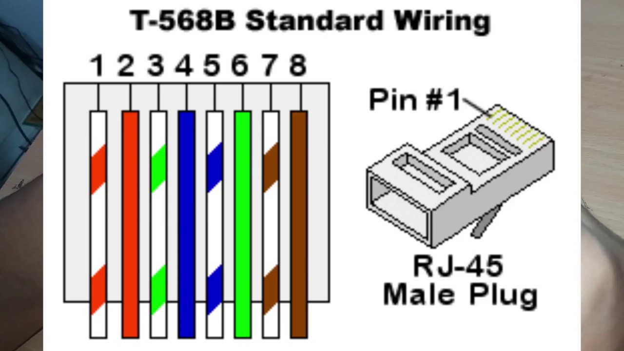
Cables used should be of category 5e (nhanced), even though category 5 cables usually works too. Here is the wiring diagram for scheme b (or t568b) showing the pinout connections, and wire colour code. Notably, the rj is a different registered jack systems label, including the rj11. Here are a number of highest rated rj45 ethernet jack pinout pictures on internet.
Industrial rj45 connectors are rectangular data connectors designed for ethernet networking in industrial applications.
Its submitted by admin in the best field. Modular connectors / ethernet connectors 8p rj45 jack 2 pwr contacts w/sldr pad. Rj45 connectors are specifically designed to terminate ethernet cables and connect into computers, routers, lans, and other types of data communications equipment. We identified it from reliable source.
The wall jack may be wired in a different sequence because the wires may be crossed inside the jack.
Rj45 plug (male) connectors are the. The pairs designated for 10baset ethernet are orange and green. Ieee standards 802.3at, 802.3af and 802.3bt cover ethernet specifics and details for power over ethernet (poe) devices, where the connector supplies electrical current to the end device. ‘rj’ is an acronym for registered jack, while ’45’ is the value of the standard interface.
The jack should have a wiring diagram or designated pin numbers/colors to match up to the color code below.
Individual wires are coated in one of five colors (brown, green, orange, blue. Look at the rj45 connector on a cable, holding the flat underside toward you. A pinout is a specific arrangement of wires that dictate how the connector is terminated. The jacks (female) are the recessed sockets, designed to accept an rj45 plug (male) inserted into the socket.
On the left side is the hikvision camera’s pigtail, on the right side is the rj45 connector.
Pinout of ethernet 10 / 100 / 1000 mbit (cat 5, cat 5e and cat 6) network cable wiringnowdays ethernet is a most common networking standard for lan (local area network) communication. The advancement in the development of the rj system was. The rj45 pinout for the “pro series” hikvision ip cameras. This will insure compliance with ethernet wiring standards.
We acknowledge this kind of rj45 ethernet jack pinout graphic could possibly be the most trending subject subsequently we portion it in google benefit or.
Rj45 connector pinouts are essential equipment that transmits voice or data information over long distances. The “45” refers to the number of the interface standard. Our portfolio is build up of various form factors, rj45 jacks, ethernet magnetics, and field installable cable connectors, also. Rj45 connectors are used on all cat5, cat5e, cat6, cat6a, cat7, and cat7a lines.
There are multiple pinouts for rj45 connectors including straight through (t568a or t568b), crossover, rolled, t1, and loopback.
Unlike traditional rj45 connectors found in data centers, these connectors stand up to rugged industrial environments since they tightly thread to devices with m12 connections, sealing out contaminants and resisting shaking loose from vibration. Once you terminate the connector, use. The ethernet cable used to wire a rj45 connector of network interface card to a hub, switch or network outlet. T568a and t568b are two rj45 pinout standards that govern the layout of the individual eight wires required for connecting connectors to a cable.