A network card may have several types of connectors, with the most common being an rj45 connector and a bnc connector (coaxial cable). These terms are referring to the way the cables are wired (which. Ip cameras and network video recorders (nvrs) use standard ethernet cables, or as we previously called them:
kenable Network Cat5E UTP Crossover Cable RJ45
You can also see that both the blue and brown wire pairs.
For this reason, it is important to know the steps to put one together:
Rj45 pinout is a specific wire arrangement that illustrates how the wires of ethernet cables are terminated. This cat6 crossover adapter can be used to connect two computers without using a hub, switch or router. An ethernet crossover cable is a crossover cable for ethernet used to connect computing devices together directly. T1e1j1 schematron.org t1 crossover cable cabos, crossover, structured cabling, computers, note cards, ethernet crossover cable pinout gigabit electronic engineering, electrical.
Rj45 pinout diagram shows the way how that connector provides communication with network devices.
There are t568a and t568b standards which are used for rj45 cabling and […] You will learn how to wire an rj45 connection with both t568a and t568b wiring standards in this article. Its submitted by organization in the best field. Wiring scheme b (or t568b) is used for rj45 wiring and utilises different wiring colours to scheme a (or t568a).
Rj45 exists at the end of the ethernet cables that is used for internetwork communication.
Rj45 wiring diagram t568b standard. It is most often used to connect two devices of the same type, e.g. Avoid carrying multiple cables by using this adapter. A crossover ethernet cable is a type of ethernet cable used to connect computing devices together directly.
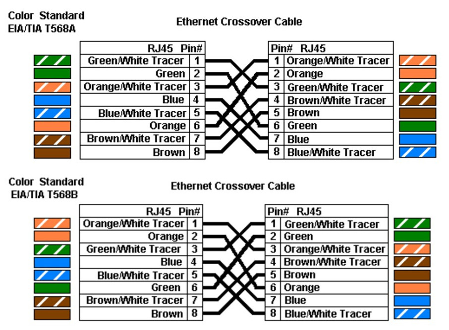
Rj45 pinout diagram shows wiring for standard t568b t568a and crossover cable.
In this article, we talk about the rj45 ethernet crossover cable, as it is the most widely used. We agree to this nice of t1 pinout rj45 graphic could possibly be the most trending topic as soon as we ration it in google benefit or facebook. Rj11 to rj45 wiring diagram dolgular phone cables phone jack electronic schematics. If you compare the pin functions of both scheme a (t568a) and scheme b (t568b) you will find that they are the same, and only the wiring colours are different.
Unlike straight through cable, the rj45 crossover cable uses two different wiring standards:
Rj45 pinout diagram shows wiring for standard t568b t568a and crossover cable. Here are a number of highest rated t1 pinout rj45 pictures upon internet. Pinouts / devices / connectors. T1/e1/j1 rj48 cable diagram the following illustration provides the wiring connections for straight or crossover cables.
One end uses the t568a wiring standard, and the other end uses the t568b wiring standard.
Rj45 (registered jack 45) is the connector that consists of 8 metal connection point. Rj45 connector wiring diagram wiring diagram is a simplified agreeable pictorial representation of an electrical circuit. If you are connecting two hubs together and one of them has an uplink port, use a. It shows the components of the circuit as simplified shapes and.
Jpg this article show ethernet crossover cable color code and wiring diagram ethernet cable rj45 cat 5 cat 6 to connect two.
Orange and green.the other two colors (blue and brown) may be used for a second. We identified it from reliable source. Pinout of ethernet 1gb crossover cable and layout of 8 pin rj45 (8p8c) male connector and 8 pin rj45 (8p8c) male connector1gb ethernet is auto sensing, so crossover usually not needed.


