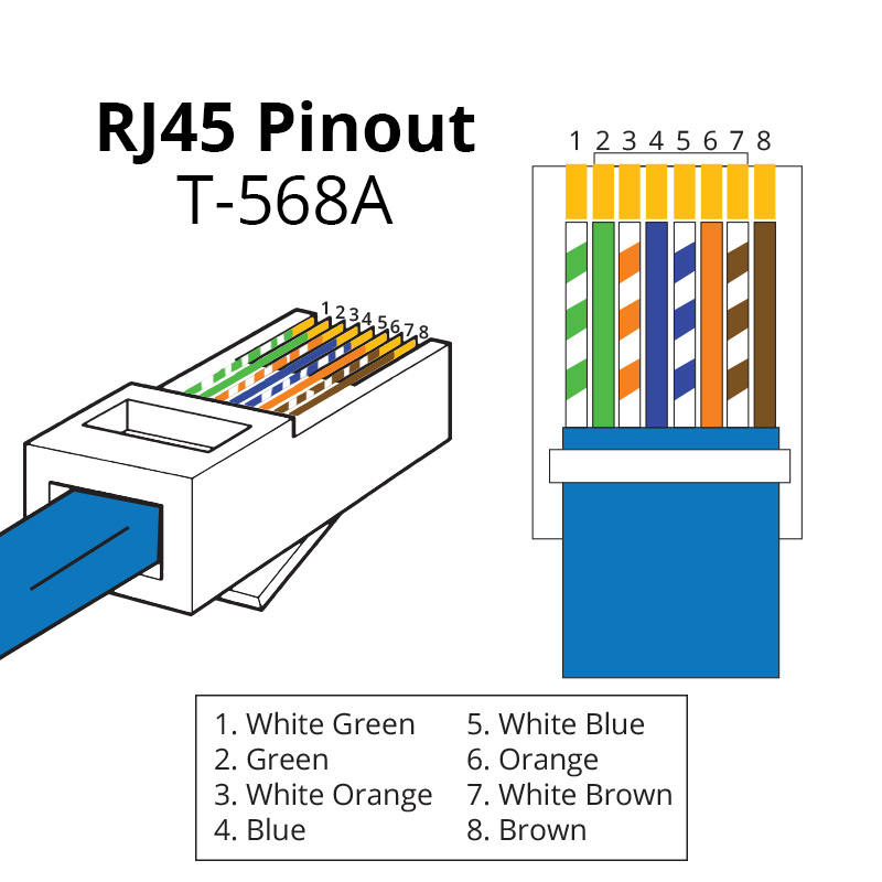
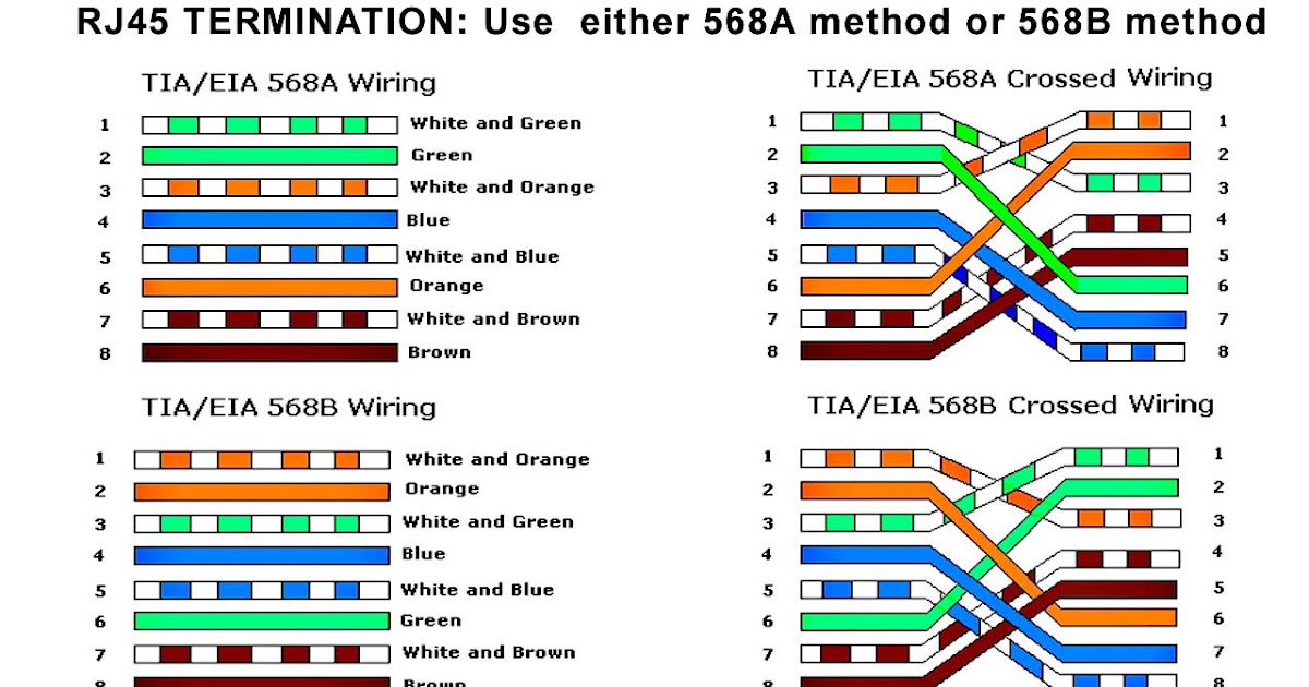
Pinout of ethernet 1gb crossover cable and layout of 8 pin rj45 (8p8c) male connector and 8 pin rj45 (8p8c) male connector1gb ethernet is auto sensing, so crossover usually not needed Please be aware that modifying ethernet cables improperly may cause loss of network connectivity. This cat5 wiring diagram and crossover cable diagram will teach an installer how to correctly assemble a cat 5 cable with rj45 connectors for regular network cables as well as crossover cables.
Easy RJ45 Wiring (with RJ45 pinout diagram, steps and
There are multiple pinouts for rj45 connectors including straight through (t568a or t568b), crossover, rolled, t1, and loopback.
T1/e1/j1 rj48 cable diagram the following illustration provides the wiring connections for straight or crossover cables.
Cat5 rj45 crossover wiring diagram. A wiring diagram usually gives counsel about the relative perspective and bargain of devices and. A crossover cable is a type of cat where one end is t568a configuration, and the other end as t568b configuration. Standards exist so technicians can know how the cable should work and can reliably alter the cable when necessary.
Two computers (via their network interface controllers) or two switches to each other.by contrast, straight through patch cables are used to connect devices of different types, such as a.
Ethernet cables and how they work. It shows the components of the circuit as simplified shapes, and the facility and signal contacts amid the devices. One end uses the t568a wiring standard, and the other end uses the t568b wiring standard. Please note that these instructions are the same for cat 6 cable and and other type of 4 twisted pair.
A crossover ethernet cable is a type of ethernet cable used to connect computing devices together directly.
In this article i will explain cat 5 color code order , cat5 wiring diagram and step by step how to crimp cat5 ethernet cable standreds a , b crossover or straight throght in order to use utp (unshielded twisted pair) cables you have to terminate both ends of cable across an rj45 (registered jack 45) connector. Cat 5 cable wiring diagram. Rj45 connector wiring diagram wiring diagram is a simplified agreeable pictorial representation of an electrical circuit. It is most often used to connect two devices of the same type, e.g.
A wiring diagram is a simplified traditional pictorial depiction of an electric circuit.
Rj45 exists at the end of the ethernet cables that is used for internetwork communication. • another way of remembering the colour coding is to. Icc rj12 6 conductor wall plate 1 port stainless steel rj45 wall socket wiring diagram. A rj45 connector is a modular 8 position, 8 pin connector used for terminating cat5e or cat6 twisted pair cable.
An ethernet crossover cable is a crossover cable for ethernet used to connect computing devices together directly.
It shows the components of the circuit as simplified shapes and. The total length of wire Figure 1 is the wiring scheme for the plug side of an rj connector. Rj45 (registered jack 45) is the connector that consists of 8 metal connection point.
It is used only for certain applications.
Rj11 to rj45 wiring diagram dolgular phone cables phone jack electronic schematics. This diagram shows how ethernet cable color coding works. Unlike straight through cable, the rj45 crossover cable uses two different wiring standards: Ethernet cable color coding diagram wiring and crossover how do rj45 utp pinout showmecables com cables colors category 6 5 cat standards pin dtcc link over rj 45 straight through vs lan tester to create an 11 network for easy with cat5 ws t568b of they work guide wall socket bt or cat6 explained tripp lite cat5e comms.
Sep 10, · the jack should have a wiring diagram or designated pin numberscolors to match up to the color code below.
Pull the cable off the reel to the desired length and cut using wire cutters or scissors. Rj45 colors and wiring guide diagram tia/eia 568a/568b how to build an ethernet cable instructions: Sun jun in specializes in rj connector rj45 rj11 developing and. Its submitted by handing out in the best field.
Cat5 rj45 crossover wiring diagram.
Internal cable structure and color coding of the wire. Alter cables at your own risk. It is one of the most commonly used cable formats for network cables. Rj45 pinout diagram shows wiring for standard t568b t568a and crossover cable.
Rj45 pinout diagram for standard t568b t568a and crossover cable are shown here.
There are t568a and t568b standards which are used for rj45 cabling and […] 4 position modular jack often called an rj11 jack or plug. You can also see that both the blue and brown wire pairs on pins 4, 5, 7, and 8 are not used in either standard. T1e1j1 schematron.org t1 crossover cable cabos, crossover, structured cabling, computers, note cards, ethernet crossover cable pinout gigabit electronic engineering, electrical.


