Peak electronic design limited ethernet wiring diagrams patch cables crossover cables token ring economisers economizers. Rj45 wiring diagram t568b standard. Adapters required to connect to various types of ports, by pinout.
Rj45 Wiring Diagram, Most Wiring Diagrams
This article illustrates the serial pinouts of opengear rj45 serial ports, past and present.
Ethernet cable wiring diagram rj.
Dahua pinout wiring diagram apart from the example shown above, many of the dahua ip cameras can have a different pinout diagram. It shows the components of the circuit as simplified shapes and. The advancement in the development of the rj system was. The rj45 pinout for the “pro series” hikvision ip cameras.
Determine the serial pinout of your opengear device.
Socket plug wiring guide tlc electrical. The following pinout examples are based on an 8pin rj45 connector and can be applied to all speed rj45 ports. Rj45 port pinouts iolan+, and at/pci fast perle iolan+ rj45 rs232 serial cable diagrams 1 (dcd) in 2 (rts) out 3 (dsr) in 4 (txd) out 5 (rxd) in Otherwise, the structure will not work as it should be.
Each part ought to be placed and connected with other parts in particular way.
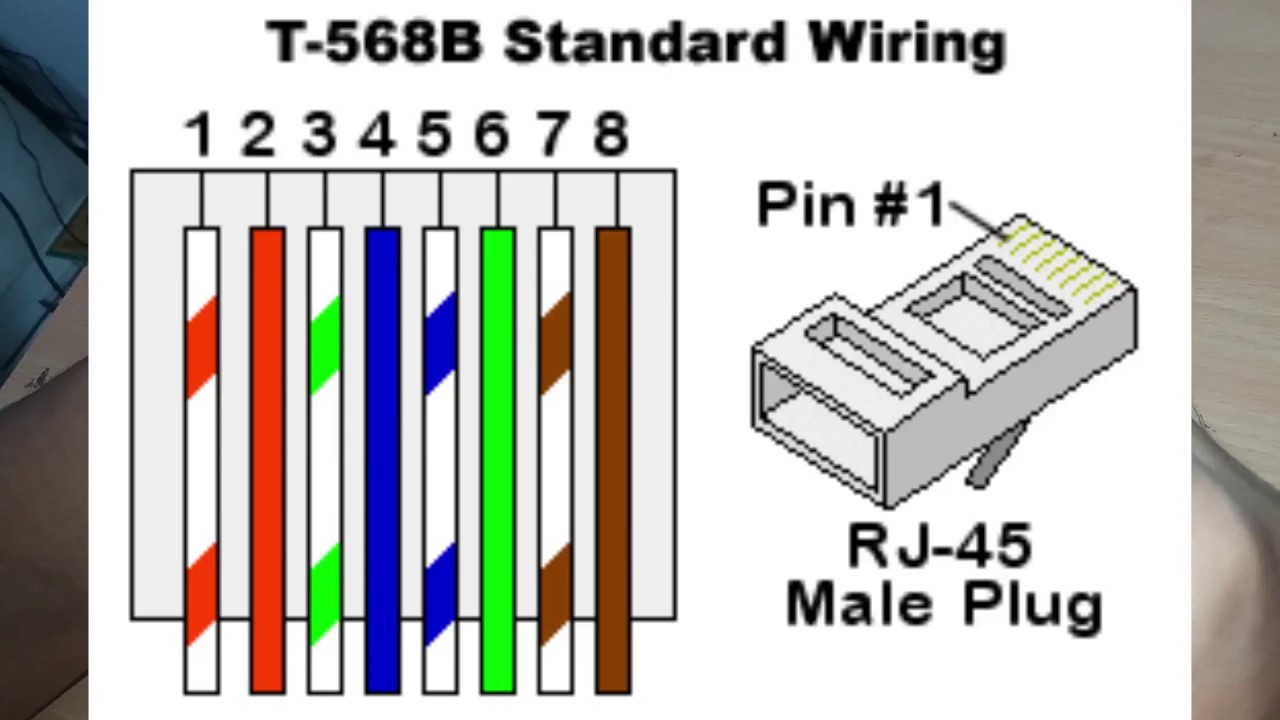
Terminal and printer connections rj45 (8pin) terminal or printer cable configuration Pull the cable off the reel to the desired length and cut using wire cutters or scissors. Rj45 pinout diagram shows wiring for standard t568b t568a and crossover cable. Rj45 colors and wiring guide diagram tia/eia 568a/568b how to build an ethernet cable instructions:
Wiring scheme b (or t568b) is used for rj45 wiring and utilises different wiring colours to scheme a (or t568a).
Cat 6 wiring diagram rj45 wiring diagrams of rj45 cat 6 wiring diagram at cat6 wire diagram ethernet wiring rj45 ethernet cable. Cat 5 wiring diagram t568b most t568a t568b rj45 cat5e is a free worksheet for you. If you compare the pin functions of both scheme a (t568a) and scheme b (t568b) you will find that they are the same, and only the wiring colours are different. Recall that there are two standards for the colors in the rj45 specification:
Sun jun in specializes in rj connector rj45 rj11 developing and.
Rj11 to rj45 wiring diagram dolgular phone cables phone jack electronic schematics. ‘rj’ is an acronym for registered jack, while ’45’ is the value of the standard interface. Icc rj12 6 conductor wall plate 1 port stainless steel rj45 wall socket wiring diagram. Sep 10, · the jack should have a wiring diagram or designated pin numberscolors to match up to the color code below.
Ethernet wall socket wiring diagram.
As there are 8 wires in every utp cables, you have to follow color coding standard on where to place each wires at rj 45 connector. Each part should be set and linked to different parts in specific manner. The steps below will help you tackle the fiddly parts of the process, while the cat 6 wiring diagram above gives you a cheat sheet to follow. The ethernet cable used to wire a rj45 connector of network interface card to a hub switch or network outlet.
A pinout is a specific arrangement of wires that dictate how the connector is terminated.
Ethernet cable pinout t568a and t568b rj45 pinout for a lan cable. Notably, the rj is a different registered jack systems label, including the rj11. Wiring scheme a (or t568a) used for rj45 wiring, utilises different wiring colours to scheme b (or t568b). A rj45 connector is a modular 8 position, 8 pin connector used for terminating cat5e or cat6 twisted pair cable.
You can also see that both the blue and brown wire pairs.
Cat6 cable wiring diagram (with an rj45 connector) wiring your own cat6 ethernet cable is easier than you might expect, at least once you have the right information. Figure 1 is the wiring scheme for the plug side of an rj connector. Rj45 connector pinouts are essential equipment that transmits voice or data information over long distances. If not, the arrangement won’t work as it ought to be.
There are multiple pinouts for rj45 connectors including straight through (t568a or t568b), crossover, rolled, t1, and loopback.
The total length of wire Another diagram may come in handy and works for most of hikvison cameras: On the left side is the hikvision camera’s pigtail, on the right side is the rj45 connector. Rj45 connector wiring diagram wiring diagram is a simplified agreeable pictorial representation of an electrical circuit.