Miner' s haven codes wiki. This tutorial uses a common cathode one. You can also use the pin p9_16 for pwm output.
Using RGB LEDs Mbed
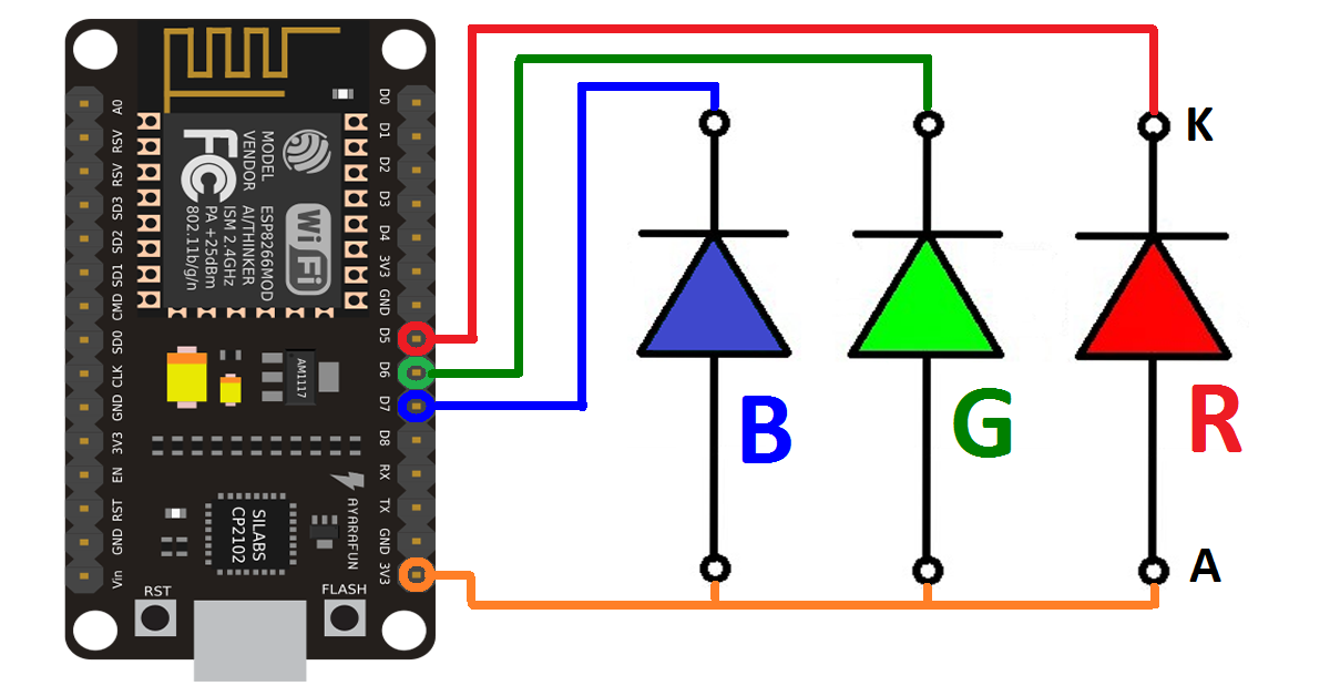
Grounding each anode will light the different colors.
To have a common cathode is standard, you connect the longest leg of the led component to the arduino board ground (gnd).
Rgb leds come in two types: I can't seem to set the led up to change color. If you only intend to light one color at the time it is sufficient to have one 220 ohm resistor on the common cathode. Refer to the pinout diagrams for hookup instructions.
The pins are numbered left to right, 1, 2 then on the next row down 3,4 etc.
Rgb led pinout common cathode. It will only blink red. Wiring of an rgb led with a common anode. B (blue) pin is used to control blue.
Zaštitarske tvrtke u hrvatskoj popis.
I got so antsy to want to control more than one rgb led, that i went to radio shack and saw they had a full color led. Longer pin goes to 5v, a 0v signal turns components on. I am playing with the make arduino starter kit i got in the last week like crazy. Common cathode and common anode.
There are also options for common anode and common cathode.
This component can be easily configured in a common cathode connection, where the ground is connected to the negative terminal and the three other pins are connected to the posiive terminal. Long story short, the wiring for the 2 do not seem to work the same, and all. There are two type of rgb leds you will encounter and they are wired very differently. Pinout diagram of the rgb led specifications of rgb led.
The three outputs to control the brightness of the red, green and blue channels are connected to sockets p8_13, p8_19 and p9_14 of the bbb.
The difference between these two wirings lies in the second lead. Ramji khand new song 2019. This is the smd rgb led common cathode module, these module has 3 separate leds the red, green and blue which can be individually driven by applying a voltage to the appropriate module pin this example code is uses the arduino analogwrite (pwm) function to cycle through the full possible output colors. I'm having some trouble setting up my rgb led.
I thought, yay, this looks exactly like the common cathode rgb led that came in my kit, i'll take 3.
Schematic diagram of rgb led. It does not matter which way around the resistors go. Rgb led circuit with an arduino layman s module how to use in driving control the l6 leds physical computing guide codrey electronics programino ide color diagram structure schematic common cathode driver smartphone operated strip amplifier for strips charlesreid1 types and light controller circuits of 20keys rf code. I want the led to cycle through colors.
The common pin can be cathode or anode, depending of the rgb led type.
Press j to jump to the feed. The common anode of the led is connected to 3.3v. To control each color, you need to apply a high signal or vcc to the red, green, and blue leads and connect the anode lead to the negative terminal of the power supply. We have used a 4017 decade counter ic which is getting clock input generated by 555timer ic.
The three outputs to control the brightness of the red, green and blue channels are connected to sockets.
Rgb led pinout common cathode. The schematic diagram can be drawn in two ways for the common anode and common cathode. Según un reporte, aproximadamente una cuarta parte del consumo de electricidad en el mundo hay que a las luces. Connect the 3 cathode legs to 220 ohm resistor and diode as shown in the circuit diagram.
How to use rgb led?
Agregar luces decorativas led como rgb led pinout common cathode es una manera simple, rentable y entretenida de añadir una enorme cantidad de energía y espíritu navideño a cualquier espacio. The led shares a common 3.3v to 5v input voltage. The rgb led is connected to the three output of the 4017 ic as the output goes high, it turns on the respected color of rgb led. The anode of the diode should be connected to the resistor.
G (green) pin is used to control green.
Latest nigerian fashion styles for ladies. In the case of the common anode, the 2 nd pin is connected to the 5v pin of the board whereas, for the common cathode, the 2 nd pin is connected to the gnd pin. It's not common anode, so it only has 2 pins. Pisanie po śladzie litery z.
The top two connections on the bbb expansion header we are using (p8) are both gnd.
As the q0, q1 and q2 output goes high red,. Push the led leads into the breadboard, with the longest (common negative) lead on the second row of the breadboard. Press question mark to learn the rest of the keyboard shortcuts In a common cathode rgb led, the cathode of the internal leds are all connected to the external cathode lead.
Circuit of rgb led driver scientific diagram.
Common cathode rgb led pinout. In common cathode leds the longer pin gets connected to gnd and its components are lit by a 5v signal, in common anode leds it’s the opposite: