Ic 555 timer is an ever green integrated circuit which has tons and tons of applications; This is based on the mosfet3205. We can achieve 220v ac at the output of just 12 volts.
Low Current Triggered Relay using 2n3904 Transistors
There are several ways to create an inverter when an engineer needs to convert dc to ac electricity.
July 21, 2020 by fariha zahid.
It is mainly used to control a high powered circuit using a low power signal. Connect the relay contacts to. It is basically an electromagnetic switch which is used in the circuit of an inverter. The relay is an engrossing component.
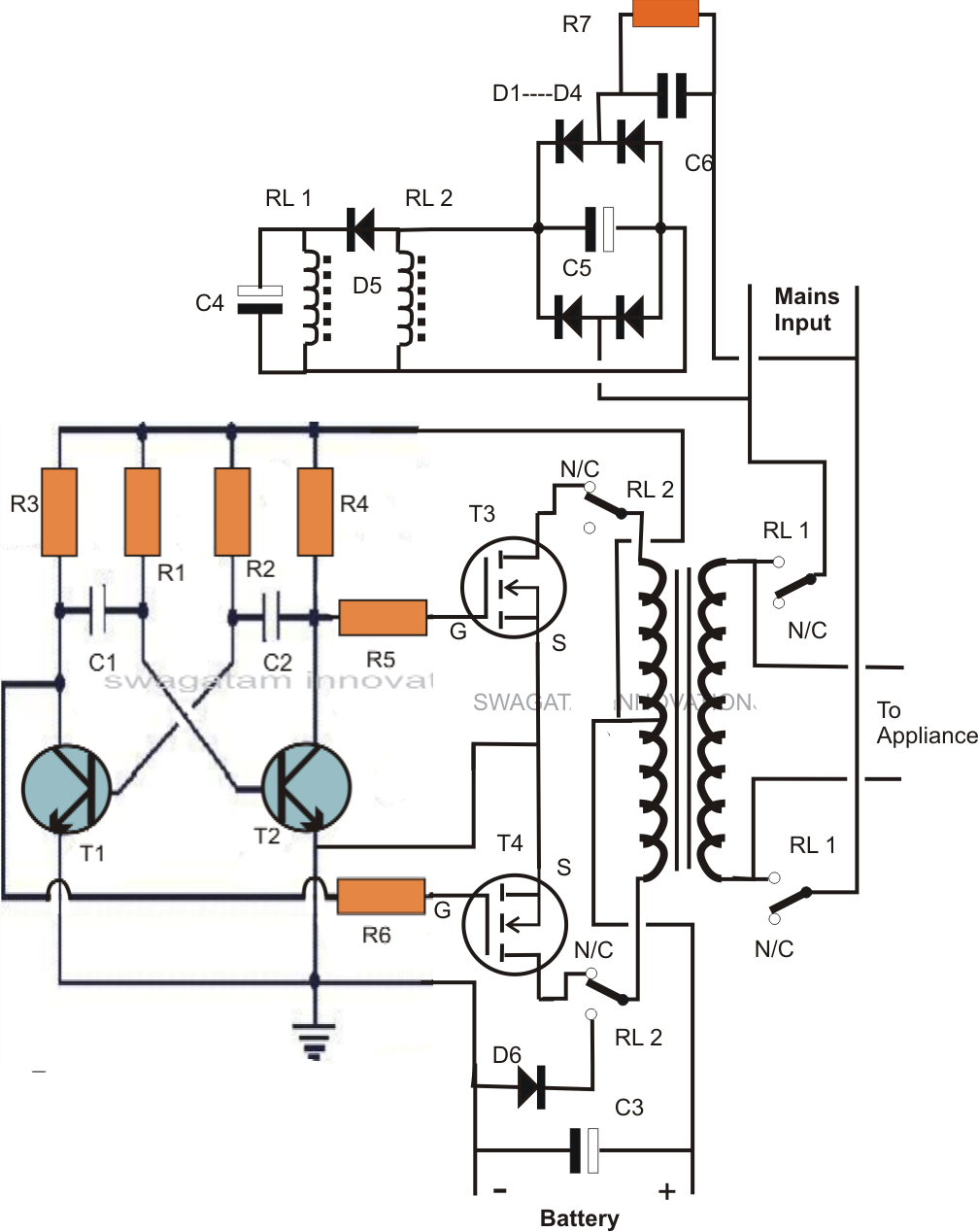
This is the circuit diagram of 2000w high power inverter circuit.
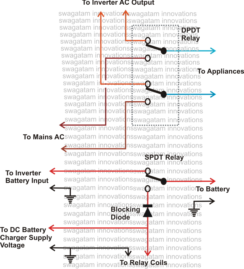
The basic idea of relay inverter is to use a relay as oscillator and switching components. The cmos gate is set up as a straightforward digital inverter. When the ac mains supply is available,the ac mains sensor senses it and the supply goes to the relay and battery charging section of the inverter.ac main sensor activates a relay and this relay will directly pass the ac mains supply to the output socket.the load will by driven by the line voltage in this situation.also the line voltage is given to the battery charging. Optocoupler relay driver with pc817 & 2n3904.
Usually there is a printing on the relay what voltage and wether ac or dc to use.
To understand the circuit you need to understand how a relay works. When relay switches the power on 12v coil on and off, the 230v coil gives around mains voltage out. A variant of the latter is for the smart load center (3000) to momentarily signal to the inverter (1000) that a circuit taking a large current is to be transferred, so that the inverter can interrupt its output for the approximately 10 milliseconds that it would take for the relay contacts to move over, and to resume inverting only after the. At the intersection of resistor r5 and capacitor c2, its output is supplied to the base of pnp transistor q1.
We can make a very reliable inverter using ic 555 and mosfets.
The main operation of this device is to make or break contact with the help of a signal without any human involvement in order to switch it on or off. Various industrial application devices make use of relays for its effective functioning. This is a must try inverter for beginners and first time diy inverter makers among hobbyists. 7 simple inverter circuits you can build at home 1) simple inverter circuit using cross coupled transistors the article deals with the construction details of a mini.
Use 24v dc supply for operation and connect 24v 5a or more than 5a transformer.
The voltage is converted up with a mains transformer, typically 12v to 230v. It works as the controller of the circuit. The relay has the differential mechanism and temperature compensation and. A relay has a coil and contacts.
The easiest way to get a light to blink (or at least the easiest to understand) is the following:
Connect +ve input power supply wire to the common pin of relay and. The functioning of the above shown triac based solid state inverter mains changeover circuit may be understood with the help of the following points: In the above circuit you see a battery, a relay (in the red square) and a light bulb. The overcurrent relays are connected in series to the load circuit and the load current is passed through.
The relay switches the power source from mains to the inverter during a power failure.
Simple inverter circuit using ic 555. Please careful with this circuit. When a single power controls a circuit, then this component is made use of to turn on and off a particular circuit. If you want the relay to switch, then you have to connect the voltage to the coil connections.
Now we have to give input power supply to the circuit.
2) the dc from the charger supply keeps t2 and the triac tr2 switched on. In this tutorial, we are going to make a circuit of the optocoupler relay driver. 1) the battery charger section is in the active state and charging the battery.