This is done to fulfill the ac load requirements. How does the pwm inverter circuit work? If you like the work and intend to build the circuit don't forget to click on the i made it.
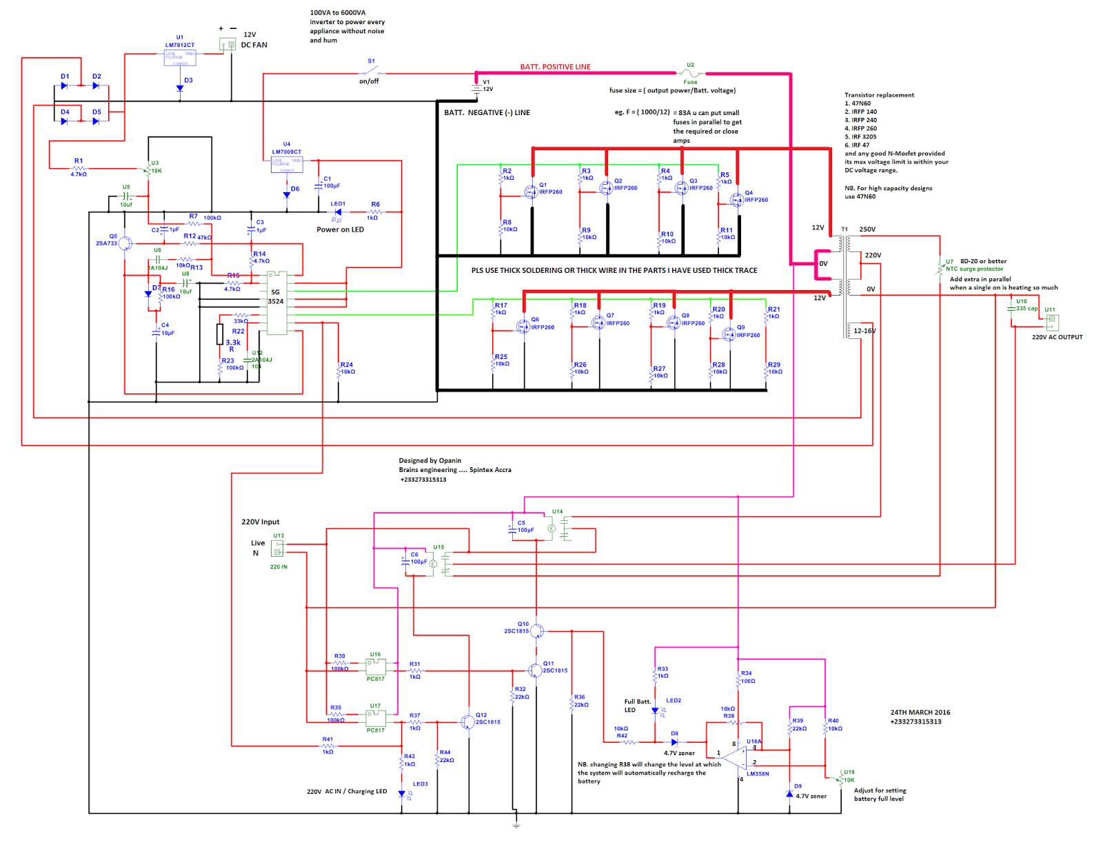
250 to 5000 Watts PWM DC/AC 220V Power Inverter Power
A modulation scheme in which the number of pulses (i.e., frequency) is varied to control the output power.
Pulse width modulated inverters usually use mosfet, and so they’re commonly called pwm mosfets inverters.
The use of mosfets in the output stage and the pwm technology makes these inverters ideal for all types of loads. I've been using it as a backup to power up all my house when outages occur since aprox. This is a heavy duty design of a pulse width modulator dc/ac inverter using the chip sg3524. Find every electronics circuit diagram here, categorized electronic circuits and electronic projects with well explained operation and how to make it procedure and then new circuits every day, enjoy and discover electronics.
Pwm or pulse width modulation is used to keep the output voltage of the inverter at the rated voltage(110v ac / 220v ac) (depending on the country) irrespective of the output load.
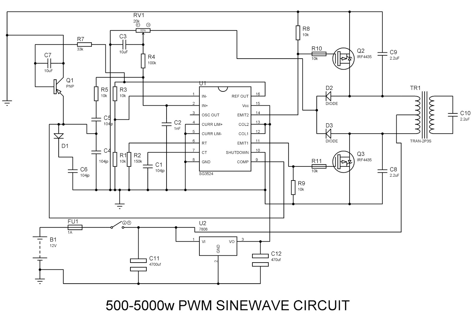
Google has not performed a legal analysis and makes no representation as to the accuracy of the status listed.) expired application number gb08234703a other versions gb2111328a (en inventor timothy f glennon The ic tl494 is a specialized pwm ic and is designed ideally to suit all types of circuits which require precise pwm based outputs. Pulse width modulation or pwm technology is used in inverters to give a steady output voltage of 230 or 110 v ac irrespective of the load. A vey basic yet reasonably efficient 1500w pwm based sinewwave inverter circuit can be studied under this post.
1500 watt pwm sinewave inverter circuit.
Using tl494 for the design. These inverters are capable of producing ac voltages of variable magnitude as well as variable frequency. Pwm inverter uses pwm (pulse width modulation) technique to control the output voltage of the inverter. A pwm inverter is a type of circuit that uses modified square waves to simulate the effects of alternating current (ac), which is suitable for powering most of your household appliances.
Pwm or pulse width modulation is used to keep the output voltage of the inverter at the rated voltage(110v ac / 220v ac) (depending on the country) irrespective of the output load.in a conventional inverter the output voltage changes according to the changes in the load.to nullify effect caused by the changing loads,the pwm inverter correct the output.
The system parameters for this converter are as follows: Here we discuss a versatile pwm based modified sine wave inverter. Vdc = 400 v fundamental frequency: 250 to 5000 watts pwm dc/ac 220v power inverter.
Pwm (pulse width modulated inverters) served as a replacement for older types of inverters.
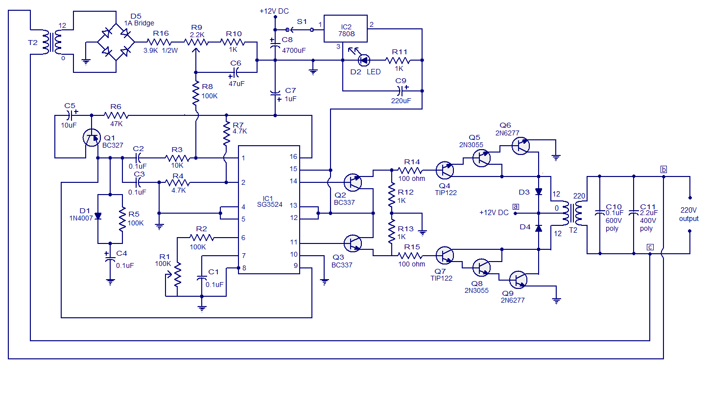
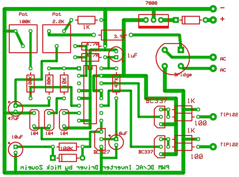
A 250w pwm inverter circuit built around ic sg3524 is shown here. A pwm inverter is a type of circuit that uses modified square waves to simulate the effects of alternating current (ac), which is suitable for powering most of your household appliances. A modulation scheme in which the pulse width (duty cycle) is varied to control the output power 2. That is to control the inverter circuit switching device on and off so that the output to give a series of equal amplitude and pulse width ranging, from using these pulses to instead of.
250w pwm inverter circuit sg3524.
An inverter is a circuit that converts direct current (dc) to alternating current (ac ). The quality of output voltage can also be greatly enhanced, when compared with those of square wave inverters. Inverters are the device which converts dc (direct current) to ac (alternating current), and gives high woltage and current from low power battery source. Semikron skm 50 gb 123d, max ratings:
The design utilizes very ordinary parts to accomplish a powerful spwm type inverter circuit.
Pwm inverter circuit diagram using ic sg3524 and mosfet. Practically these are used in the power electronics circuits. In most cases, companies use them in the creation of power electronic circuits. Here is a simple pwm dc to ac voltage inverter circuit based on ic sg 3524.
Pulse width modulated inverters (pwm inverter) replaced the older versions of inverters and has a wide range of applications.
Inverters are very helpful to operate electrical appliances during power cut or shortage, inverters can be classified based on the output terms like, square wave, modified sine wave and pure. In a conventional inverter, the output voltage changes according to the changes in the load. F = 60 hz pwm (carrier) frequency: In pwm inverter the controlled output is obtained by adjusting the on and off periods of the inverter components.
Most of the inverters available nowadays possess this pwm technology and are capable of.
The power of the inverter is essentially contingent on the transformer wattage as well as the battery ah specifications, one can possibly modify most of these variables in respect to personal preference. Sg3524 pwm inverter circuit diagram. The inverters based on the pwm technology possess mosfets in the switching stage of the output. The sg3524 ic integrated circuit has all the functions necessary for the production of a regulating power.
An inverter is a circuit that converts direct current (dc) to alternating current (ac).