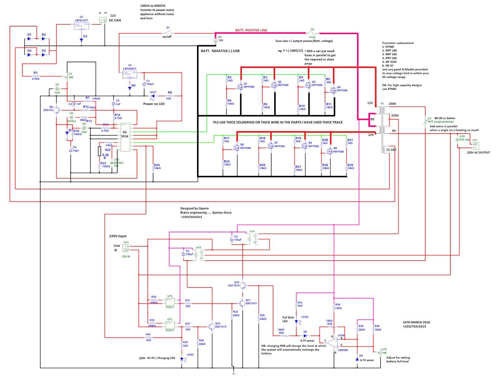
Circuit diagram of 250w pwm inverter. Single phase full bridge inverter. Here is a simple pwm dc to ac voltage inverter circuit based on ic sg 3524.
SG3524 PWM INVERTER CIRCUIT Many circuits
The ic tl494 is an ideal pwm ic which is intended essentially to match all sorts of circuits which necessitate accurate pwm dependent outputs.
1 for all pwm techniques.
The inverters based on the pwm technology possess mosfets in the switching stage of the output. The bd135 transistor along with its base zener provides a stabilized voltage to the associated electronics for sustaining constant pwm output from the relevant ics. Many drawbacks and flaws were detected while assessing. Practically these are used in the power electronics circuits.
Circuit diagrams of example below show the circuit diagram of sg3525 which generates two inverted pwm signals.
Preset r1 can be used for fine tuning of the oscillator frequency. In case of the current source inverter, the rectify is linked with the inverter through the large series inductors ls. This document describes inverter circuits used for motor control and other applications, focusing on pwm control. Pulse width modulated inverters (pwm inverter) replaced the older versions of inverters and has a wide range of applications.
By debashis das mar 04, 2020 2.
In order to increase the efficiency of the pwm inverter, the electronic circuit is highly sophisticated with battery charge sensor, ac mains sensor, soft start facility, output control etc. This is a heavy duty design of a pulse width modulator dc/ac inverter using the chip sg3524. Pulse width modulation in electronic power converters and motors, pwm is used extensively as a means of powering alternating current (ac) devices with an available direct current (dc) source or for advanced dc/ac conversion. The circuit diagram of the pwm inverter remains the same as which is shown in the following fig.
Shift pwm, which can reduce the power losses and emi for the system based on the prediction model.
Igbt is a mosfet and gtr composite device, so it has work fast, big input impedance, simple driving circuit, simple control circuit, higher operating. Acces pdf freedom 10 inverter circuit diagram freedom 10 inverter circuit diagram yeah, reviewing a books freedom 10 inverter circuit diagram could ensue your close associates listings. This inverter circuit contains three stages, pwm switching pulse generator; Users can adjust the width of pwm using a variable resistor shown in the feedback circuit.
Sg3524 pwm inverter circuit diagram.
Pwm or pulse width modulation is used to keep the output voltage of the inverter at the rated voltage(110v ac / 220v ac) (depending on the country) irrespective of the output load.in a conventional inverter the output voltage changes according to the changes in the load.to nullify effect caused by the changing loads,the pwm inverter correct the output. The intersection of and waves determines the switching instants and commutation of the modulated pulse. Pwm modified sine wave inverter circuit. Resistor r2 and capacitor c1 sets the frequency of the ics internal oscillator.
250 to 5000 watts pwm dc/ac 220v power inverter.
With irf1404 as the mosfets, the inverter would be able to generate anywher around 300 to 5000 watts of pure sine wave output. Most of the inverters available nowadays possess this pwm technology and are capable of. Shows the complete circuit diagram of the pwm inverter circuit. You can change the variable resistor value to adjust the resolution of pwm.
12 rows pwm inverter circuit using tl494.
Advantages of using pwm (pulse width modulation). Current source inverters and voltage source inverts can seen in below figure. I've been using it as a backup to power up all my house when outages occur since aprox. Pin 14 and pin 11 are the emitter terminals of the internal driver transistor of the ic.
Simple and powerful pwm inverter circuit diagram designed with ic sg3524 (regulating pulse width modulator) gives upto 230v ac from 12v dc supply.
Find every electronics circuit diagram here, categorized electronic circuits and electronic projects with well explained operation and how to make it procedure and then new circuits every day, enjoy and discover electronics. In the above circuit diagram feedback from the output is used to get regulated voltage. If you like the work and intend to build the circuit don't forget to click on the i made it. Download scientific diagram | circuit diagram of pwm inverter section from publication:
Here we discuss a versatile pwm based modified sine wave inverter circuit.
The sg3524 ic integrated circuit has all the functions necessary for the production of a regulating power. The pwm controller circuit uses pwm ic ka 3225 or lm 494.these ics have internal circuits for the entire operation of the pulse width modulation.