Op amp 2 as an inverter. First with a double voltage module voltage for the op amp power supply. The pure sine wave inverter has various applications because of its key advantages such as operation
Pure Sine Wave Inverter, Using IC 555
Here we are mainly using the internal oscillator of pwm sg3525.
All in all, says this is a 24v pure sine wave inverter, this power inverter is composed of three parts:
Op amp 1 generates a 50 hz sine wave as the reference signal. Experiment, if a pair of 190n08, totem part can be omitted, directly 3525 driven enough. The icl7660 or max1044 can be selected. Even top inverters manufacture companies also use sg3525 in dc to dc converter part of the inverter.
Sg3525 is a voltage mode pwm controller integrated circuit.
25va and later on 80va. This is an sg3525 based inverter schematic. Inverter circuits are too many. And we will build the 12v to 230v inverter circuit using pwm ic sg3525.
Sine wave inverter circuit diagram with complete step by step program and coding, in this article i will discuss how to use push pull converter, sinusoidal pulse width modulation, h bridge and low pass lc filter to make pure sine wave inverter circuit diagram.
1kva 1000 watts pure sine wave inverter circuit electrical engineering world electronic circuit projects circuit diagram electronic circuit. A modified sine wave can be seen as more of a square wave than a sine wave; Using the sg3525 pwm controller explanation and example circuit diagram schematic of push pull converter. 3 phase inverter circuit diagram the internet is flooded with single phase inverter circuit diagrams but there are only few circuit diagrams of 3 phase inverter out there.
Pwm (pulse width modulation) signal based inverters are produce output as pure sine wave and it can be used for any electric appliance that meets the inverter output range.
It is used in maximum inverters available in the market. It passes the high dc voltage for specified amounts of time so that the average power and rms voltage are the same as if it were a sine wave. Utilizing pwm and analog components, the utilizing pwm and analog components, the output will be a clean sinusoid, with very little switching noise, combined with the inexpensive the microcare pure sine wave inverters deliver true clean sine wave output […] Then i want to use a microcontroller to make a pwm to make a sine @ 230vac 50hz.
Modified sine wave, and pure sine wave1.
When this part of the circuit sg3525 application that uses shallow closed loop modulation, the principle is to sg3525 2 feet of introducing a fixed reference, it is now 5v. 800va pure sine wave inverter’s reference design sanjay dixit, ambreesh tripathi, vikas chola, and ankur verma abstract this application note describes the design principles and the circuit operation of the 800va pure sine wave inverter. 12v to 220v dc ac converter inverter circuit diagram with pcb. Pure sine wave inverter circuit diagram pdf efficient, inexpensive inverter with a pure sine wave output.
3 high power sg3525 pure sinewave inverter circuits homemade circuit projects.
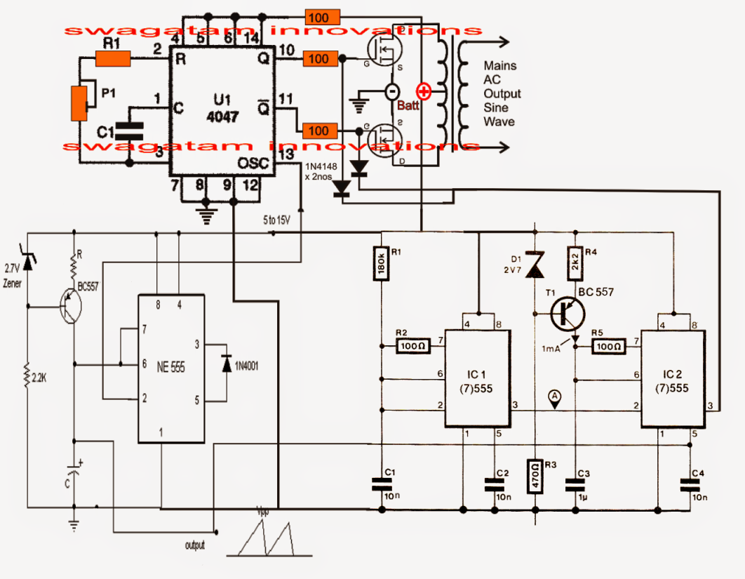
It is a 16 pin integrated circuit. The spwm accuracy of eg8010 was not high enough waveform, so the inverter output was not good enough as pure sine wave. Layout, circuit diagram and its applicationsautomatic ups / inverter wiring & connection diagram to 800va pure sine wave inverter's reference design (rev. Image shows the complete circuit diagram of the sinewave inverter, the images are divided into two in order to fit inside the page, please join them together after printing the two images.
Sine wave inverter circuit using pic16f72 pure sinewave inverter using.
It has two pwm outputs both are an inversion of each. Simple and powerful pwm inverter circuit diagram designed with ic sg3524 (regulating pulse width modulator) gives upto 230v ac from 12v dc supply. Now i think it’s time to introduce an inverted that has one of the best inverter efficiency. Design of single phase sine wave spwm inverter power supply based on sg3525.