One measure of the purity of a sine Block diagram from dc/ac pure sine wave inverter mqp the report provided a summative perspective of pwm sine wave inverters, but shortcomings of the project can be noted. Pure sine wave inverter circuit diagram pdf efficient, inexpensive inverter with a pure sine wave output.
300 Watts PWM Controlled, Pure Sine Wave Inverter Circuit
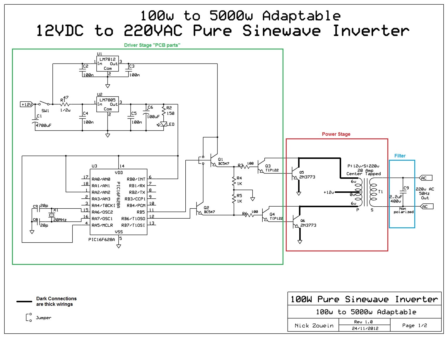
The following image shows the complete circuit diagram of the sinewave inverter, the images are divided into two in order to.
Pure sine wave inverter circuit of spwm.
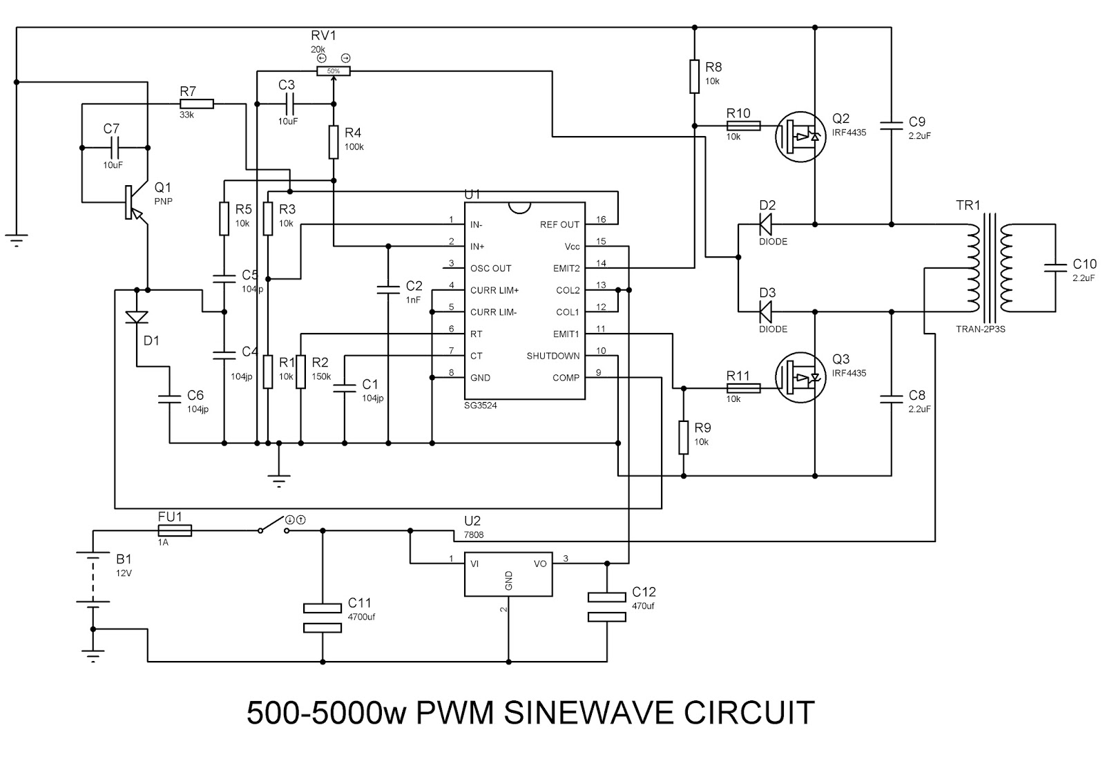
You just have to program the arduino board. Sine wave inverter circuit using pic16f72. With irf1404 as the mosfets, the inverter would be able to generate anywher around 300 to 5000 watts of pure sine wave output. Few days ago, gohz made a 24v 2000w power inverter in home, sharing some design schematics and circuit diagrams.
250w pwm inverter circuit sg3524.
Pwm (pulse width modulation) signal based inverters are produce output as pure sine wave and it can be used for any electric appliance that meets the inverter output range. In this article we carry on the design a little ahead and learn how it can be enhanced into a pure sine wave inverter circuit using a couple. Lower voltage limit :110+ 5v lower recovery voltage :120+ 5v mains a.c. The built in circuitries inside the sg3524 include pulse width modulator, oscillator.
The post details comprehensively regarding how to build a pure sinewave inverter circuit using microcontroller circuit with pic16f72.
2000 watt pure sine wave inverter circuit diagram. Op amp 2 as an inverter. [thienbaogroup_dau] earlier than finding out the varied designs defined on this article, it could be fascinating to know the components which generally makes a sine wave inverter. The square wave is fed to ic 4017 which will convert to modified sine wave at 50hz at 50% duty cycle.
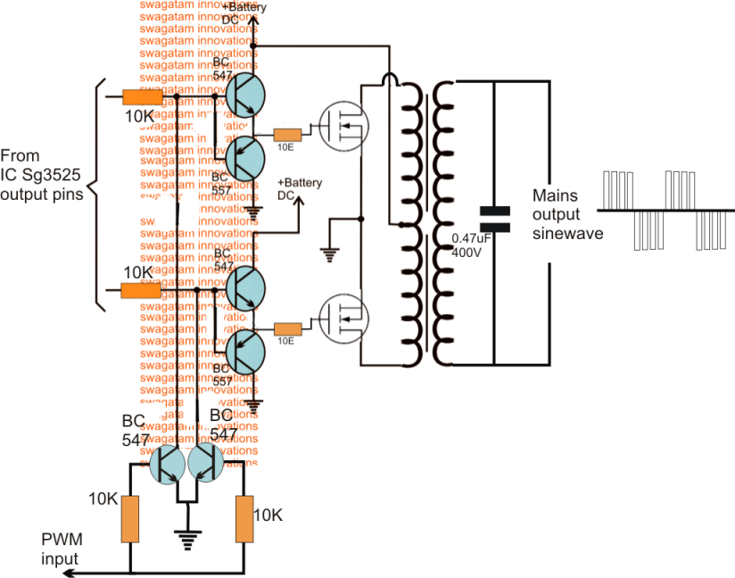
The post explains a 3 powerful yet simple sine wave 12v inverter circuits using a single ic sg 3525.
Make this 1kva (1000 watts) pure sine wave inverter circuit circuit diagram: First with a double voltage module voltage for the op amp power supply. Op amp 1 generates a 50 hz sine wave as the reference signal. Simple and powerful pwm inverter circuit diagram designed with ic sg3524 (regulating pulse width modulator) gives upto 230v ac from 12v dc supply.
The put up explains a number of circuit ideas which could be employed for changing or modifying any unusual sq.
Many drawbacks and flaws were detected while assessing. 2 600 watt pure sine wave inverter. 100w to 3kva make your own full explanation kayal manufacturer pure 1000w 24v solar s home 3000w lz2gl 1500 watt pwm sinewave egs002 resources easyeda 3000 120v ato customized 48v suppliers manufacturers factory whole ssth 1500w from shenzhen heng ye da elec co ltd charger. 800va pure sine wave inverter’s reference design sanjay dixit, ambreesh tripathi, vikas chola, and ankur verma abstract this application note describes the design principles and the circuit operation of the 800va pure sine wave inverter.
Let's learn the details below.
The pure sine wave inverter has various applications because of its key advantages such as operation Pure sine wave inverter project: In a previous article, i have shown you how. 275+ 5v higher recovery voltage :
A 250w pwm inverter circuit built around ic sg3524 is shown here.
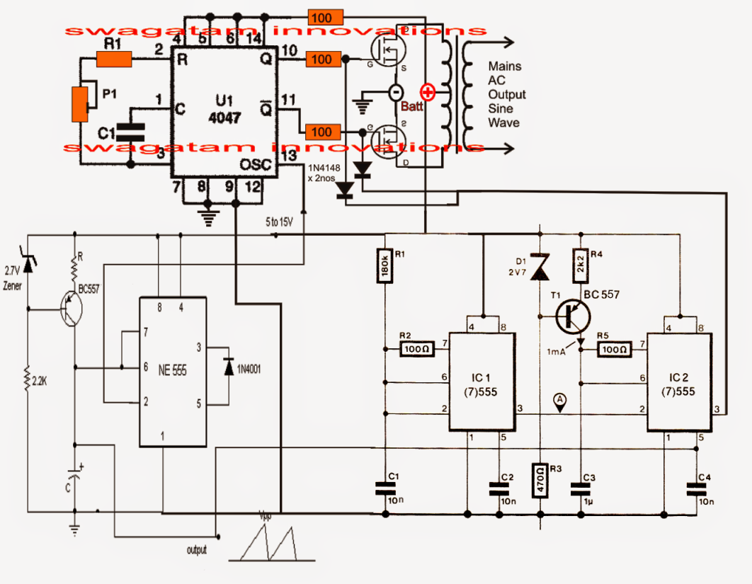
Last updated on april 20, 2020 by admin 57 comments. Modified sine wave inverter circuit diagram the circuit consists of ic 555 which is tuned to generate frequency at 200hz (square wave) at 50% duty cycle. Utilizing pwm and analog components, the output will be a clean sinusoid, with very little switching noise, combined with the inexpensive manufacturing that comes with an analog approach. Sine wave pwm (spwm) circuit using opamp.
Wave inverter to a subtle sine wave inverter design.
Efficient, inexpensive inverter with a pure sine wave output. This report documents the design of a true sine. Utilizing pwm and analog components, the utilizing pwm and analog components, the output will be a clean sinusoid, with very little switching noise, combined with the inexpensive the microcare pure sine wave inverters deliver true clean sine wave output […] In the previous post we discussed the main specifications and datasheet of the ic 4047 where we learned how the ic could be configured into a simple inverter circuit without involving any external oscillator circuit.
The diagram below shows the circuit diagram of sinusoidal pulse width modulation with two output both are on alternatively after every 10 ms.
The spwm accuracy of eg8010 was not high enough waveform, so the inverter output was not good enough as pure sine wave. These pure sine wave inverters are very expensive, where the modified square wave inverters are inexpensive. Voltage limits (inverter mode) : The first circuit is equipped with a low battery detection and cut off feature, and an automatic output voltage regulation feature.
Sine wave inverter circuit pure sine wave inverter circuit using ic 4047 last updated on august 3, 2020by swagatam596 comments a very effective pure sine wave inverter circuit can be made using the ic 4047 and a couple ic 555 together with a few other passive components.
Spwm refers to sine wave pulse width modulation which is a pulse width arrangement in which the pulses are narrower at the start, which gradually get broader at the middle, and then narrower again of the end of the arrangement. This set of pulses when implemented in an inductive application like. An inverter circuit is used to convert dc power to ac power and it can be divided into two types that is pure sine wave inverters or modified square wave inverters. In the last article we learned how to generate sine wave pulse width modulation or spwm though arduino, we are going to use the same arduino board to make the proposed simple pure sine wave inverter circuit.the design is actually extremely straightforward, as shown in the following figure.
The bd135 transistor along with its base zener provides a stabilized voltage to the associated electronics for sustaining constant pwm output from the relevant ics.
Learn more about different types of inverter here. 3 high power sg3525 pure sinewave inverter circuits.