The project is based on the low cost egs002 spwm driver board module. Diy cheap 1000w pure sine wave inverter (12v to 110v/220v): 2000 watt pure sine wave inverter circuit diagram wiring diagram line wiring diagram.
Pure Sine Wave Inverter Circuit Diagram Pdf Circuit
Sine wave inverter circuit diagram with complete step by step program and coding, in this article i will discuss how to use push pull converter, sinusoidal pulse width modulation, h bridge and low pass lc filter to make pure sine wave inverter circuit diagram.
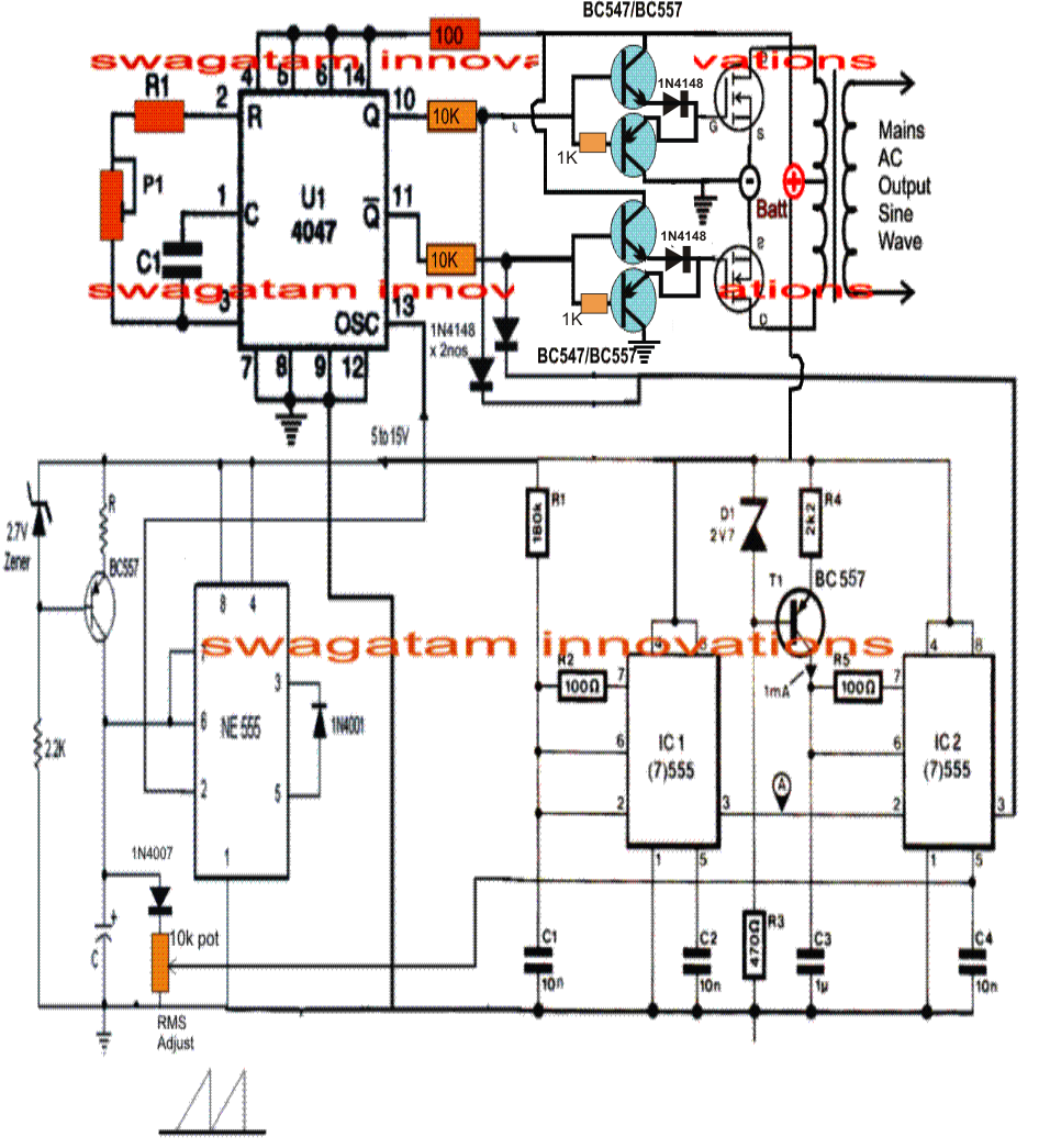
Modified sine wave inverter circuit diagram the circuit consists of ic 555 which is tuned to generate frequency at 200hz (square wave) at 50% duty cycle.
A modified sine wave can be seen as more of a square wave than a sine wave; It comprises a cd4047 multivibrator (ic1), irf250 mosfets (t1 through t8), transistors and a few discrete components. Make this 1kva (1000 watts) pure sine wave inverter circuit circuit diagram: It passes the high dc voltage for specified amounts of time so that the average power and rms voltage are the same as if it were a sine wave.
I have already discuss all these topics in following articles.i.
The first circuit is equipped with a low battery detection and cut off feature, and an automatic output voltage regulation feature. Car batteries for powering you home? Lower voltage limit :110+ 5v lower recovery voltage :120+ 5v mains a.c. The square wave is fed to ic 4017 which will convert to modified sine wave at 50hz at 50% duty cycle.
Circuit connection of solar in a house.
275+ 5v higher recovery voltage : Easy home made inverter you can make also in hindi grow amis. The icl7660 or max1044 can be selected. Tìm kiếm các công việc liên quan đến pure sine wave inverter circuit diagram circuit hoặc thuê người trên thị trường việc làm freelance lớn nhất thế giới với hơn 21 triệu công việc.
In a previous article, i have shown you how.
Sine wave inverter circuit using pic16f72. Pure sine wave inverter circuit diagram. China parrael connection solar inverter home 5kva 4000w 48v 230v pure sine wave power. 6 best simple inverter circuit diagrams diy electronics projects.
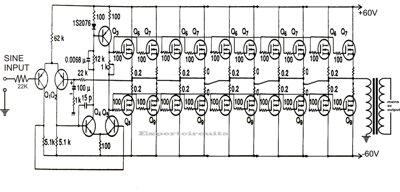
As can be seen in the first diagram below, the configuration is a simple mosfet based designed for amplifying.
These pure sine wave inverters are very expensive, where the modified square wave inverters are inexpensive. Miễn phí khi đăng ký và chào giá cho công việc. 3 high power sg3525 pure sinewave inverter circuits. Two types of inverters currently exist on the market;
Last updated on august 3, 2020 by swagatam 241 comments.
800va pure sine wave inverter’s reference design sanjay dixit, ambreesh tripathi, vikas chola, and ankur verma abstract this application note describes the design principles and the circuit operation of the 800va pure sine wave inverter. Op amp 2 as an inverter. An inverter circuit is used to convert dc power to ac power and it can be divided into two types that is pure sine wave inverters or modified square wave inverters. 2000 watt pure sine wave inverter circuit diagram wiring diagram line wiring diagram.
600w pure sine wave power inverter circuit principle:
The following image shows the complete circuit diagram of the sinewave inverter, the images are divided into two in order to fit inside the page, please join them together after. Voltage limits (inverter mode) : The inverter is divided into four parts, each part make a pcb board. First with a double voltage module voltage for the op amp power supply.
Here is the 600 watt inverter pure sine wave prototype photos and operation wave forms:
Wave inverter to a subtle sine wave inverter design. I have included circuit diagram using igbt, pic18f886 circuit diagram, assembly language program for pic16f886 and hex file in pdf format. The pure sine wave inverter has various applications because of its key advantages such as operation Pure sine wave inverter project:
Make this 1kva (1000 watts) pure sine wave inverter circuit.
230v, 50hz, 1.5kva, full bridge pure sine wave inverter circuit using sinusoidal pulse width modulation. 2000w inverter circuit diagram high power homemade 2000 va projects with diagrams gohz com siwire 12v simple china dc ac 220v photos pictures made in 7 modified. The post details comprehensively regarding how to build a pure sinewave inverter circuit using microcontroller circuit with pic16f72. Sine wave inverter circuit description.
Op amp 1 generates a 50 hz sine wave as the reference signal.
Utilizing pwm and analog components, the utilizing pwm and analog components, the output will be a clean sinusoid, with very little switching noise, combined with the inexpensive the microcare pure sine wave inverters deliver true clean sine wave output […] The put up explains a number of circuit ideas which could be employed for changing or modifying any unusual sq. Modified sine wave, and pure sine wave1. The diy inverter board can handle up to 1kw (depending the transfor…
Dc/ac pure sine wave inverter.
How to connect a solar panel an existing inverter circuit diagram hybrid system. The post explains a 3 powerful yet simple sine wave 12v inverter circuits using a single ic sg 3525. Pure sine wave inverter circuit diagram pdf efficient, inexpensive inverter with a pure sine wave output. Few days ago, gohz made a 24v 2000w power inverter in home, sharing some design schematics and circuit diagrams.
The spwm accuracy of eg8010 was not high enough waveform, so the inverter output was not good enough as pure sine wave.
Learn more about different types of inverter here. This is accomplished through an inverter circuit using electronic components. A relatively simple 1000 watt pure sine wave inverter circuit is explained here using a signal amplifier and a power transformer. Here the project report of dc/ac pure sine wave inverter.