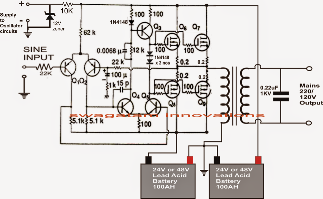
It passes the high dc voltage for specified amounts of time so that the average power and rms voltage are the same as if it were a sine wave. Low voltage due to the inability to step up dc voltage at the time and thus it was not capable of transmitting. As can be seen in the first diagram below, the configuration is a simple mosfet based
Draw your wiring Pure Sine Wave Inverter Circuit Diagram Pdf
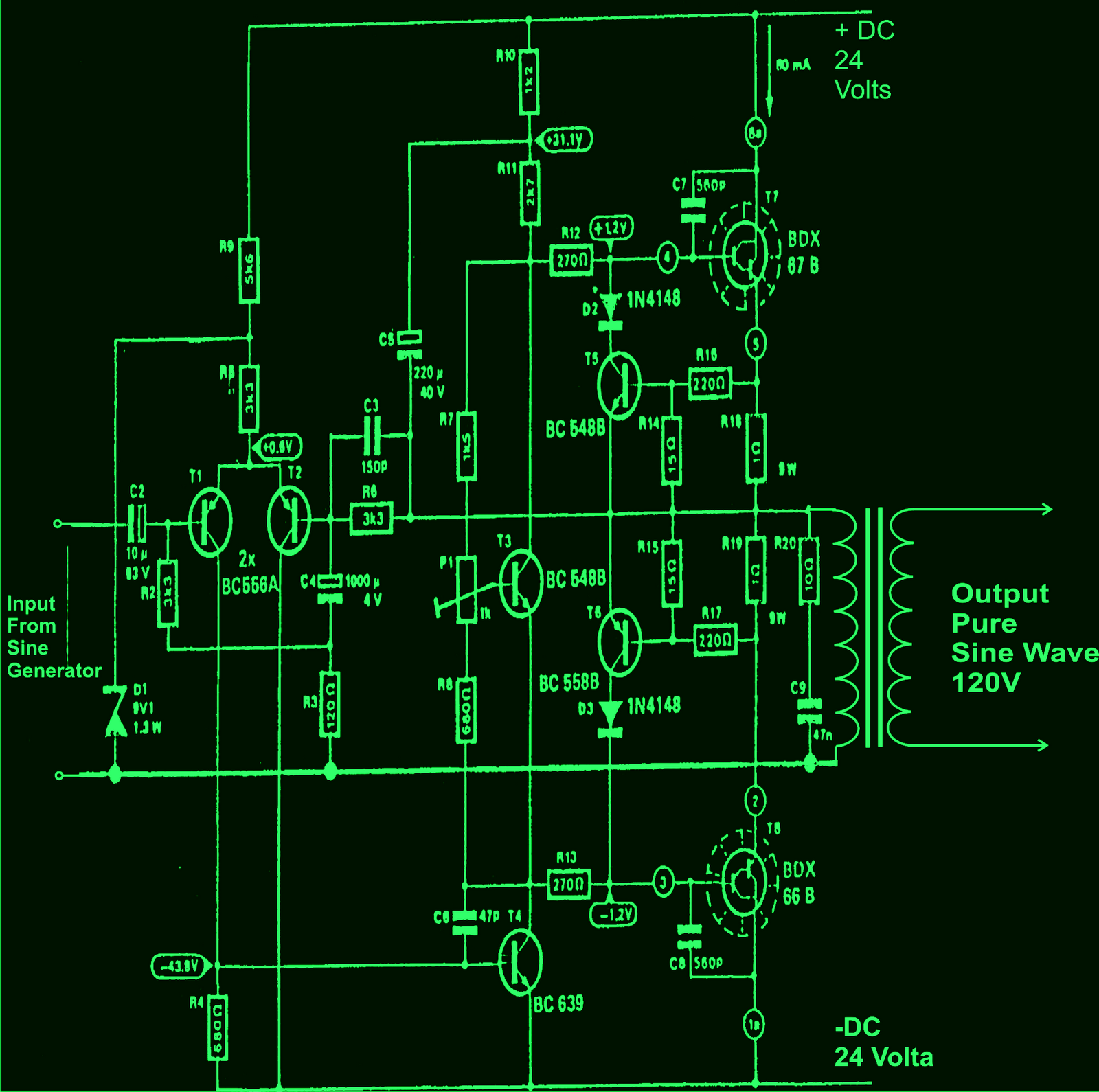
And the circuit operation of the 800va pure sine wave.
January 2, 2014 at 8:37 pm.
But in power system use of power converters inject harmonics and voltage wave form distortion in main power supply. Hopefully the pictures above wiring diagram can be useful. 800va pure sine wave inverter’s reference design sanjay dixit, ambreesh tripathi, vikas chola, and ankur verma abstract this application note describes the design principles and the circuit operation of the 800va pure sine wave inverter. In such cases ups is used to provide pure sine wave to load.
Modified sine wave, and pure sine wave1.
These values are agreeing with the voltage and frequency of the grid, the Wave figure 7 shows that proposed hardware setup of the implementation inverter circuit to obtain sinusoidal wave ac output voltage with a rated voltage magnitude of 221 v ac and frequency 50hz. A) few days ago, gohz made a 24v 2000w power inverter in home, sharing some design schematics and circuit diagrams. The pure sine wave inverter has various applications because of its key advantages such as operation
In case of emergency breakdown when utility power is not available from the power house we may use automatic inverter ups and batteries to connect.
A relatively simple 1000 watt pure sine wave inverter circuit is explained here using a signal amplifier and a power transformer. Dc/ac pure sine wave inverter pdf document. Zinnaboy, you will have to make the circuit exactly as its presented, 2uf should be 2uf only, any other value will not do, use two 1uf caps in parallel. Ups uninterruptible power supply circuit diagram similarly there are many devices which need pure sine wave to operate properly.
8/10/2017 · there’s pretty easy to make square wave inverter circuit in the internet.
Sine wave inverter circuit diagram with complete step by step program and coding, in this article i will discuss how to use push pull converter, sinusoidal pulse width modulation, h bridge and low pass lc filter to make pure sine wave inverter circuit diagram. Inverter is the dc to ac voltage conversion. Sine wave inverter circuit diagram with complete step by step program and coding, in this article i will discuss how to use push pull. Modified sine wave inverter circuit diagram the circuit consists of ic 555 which is tuned to generate frequency at 200hz (square wave) at 50% duty cycle.
Related book pdf book pure sine wave inverter circuit diagrams free download :
In the course of guides you could enjoy now is pure sine wave inverter circuit diagram below. This report focuses on dc to ac power inverters, which aim to efficiently transform a dc power source to a high voltage ac source, similar to power that would be available at an electrical wall outlet. This is accomplished through an inverter circuit using electronic components. In order to get the best used effect.
International journal of engineering research & technology (ijert) issn:
This project is a difficult project and is recommended for experts so please be. 800va pure sine wave inverter's reference design (rev. View pdf sukam sine wave inverter circuit diagram pictures. The square wave is fed to ic 4017 which will convert to modified sine wave at 50hz at 50% duty cycle.
So we try to make an inverter which output is nearly pure sine wave.
They use batteries to generate power and it’s important to have a means of recharging (cunningham, 1999) [3]. But the sine wave inverters are costly than other inverters. 1000w inverter pure sine wave schematic diagram datasheet. We have so many collections wire wiring diagrams and schematics, possibly including what is you need, such as a discussion of the inverter circuit diagram 1000w pdf.
These pure sine wave inverters are very
A modified sine wave can be seen as more of a square wave than a sine wave; Two types of inverters currently exist on the market; Please put the inverter on the flat surface, example the Ashwini kumari 1,2 departmentof electrical and electronics engineering, ritm engineering college, bangalore, india abstract—with the increase in the.
It's wave form is the same with the commercial electric power.the general load power is driven by the inverter unless the load power is higher than the output of the inverter.
Make this 1kva (1000 watts) pure sine wave inverter circuit circuit diagram: It is your completely own become old to do something reviewing habit. This manual contains all the instructions about safety, installation, and operation for the ipower plus series pure sine wave inverter (shown as inverter in the rest of the manual). The output wave form is the pure sine wave.
But to run most load like fan, tv, etc you need to have a sine wave inverter.
100mh (0.1h) inductor, make sure you get high amperes rating ones.


![[PDF] Design and Construction of a Pure Sine Wave Inverter](https://i2.wp.com/d3i71xaburhd42.cloudfront.net/2bac87c960c27de48e70d4782434f65e528ddfa2/3-Figure1-1.png)

