An inverter circuit is used to convert dc power to ac power and it can be divided into two types that is pure sine wave inverters or modified square wave inverters. It comprises a cd4047 multivibrator (ic1), irf250 mosfets (t1 through t8), transistors and a few discrete components. Aliali556352@gmail.comavailable [code + simulation + pcb.
EGS002 SINE WAVE INVERTER CIRCUIT Many circuits
Rectifier (to convert 220v ac to dc) 2.
The post explains a 3 powerful yet simple sine wave 12v inverter circuits using a single ic sg 3525.
Few days ago, gohz made a 24v 2000w power inverter in home, sharing some design schematics and circuit diagrams. A relatively simple 1000 watt pure sine wave inverter circuit is explained here using a signal amplifier and a power transformer. As can be seen in the first diagram below, the configuration is a simple mosfet based designed for amplifying. The first circuit is equipped with a low battery detection and cut off feature, and an automatic output voltage regulation feature.
Modified sine wave, and pure sine wave1.
The above diagram clearly shows the component in my circuit. I have included circuit diagram using igbt, pic18f886 circuit diagram, assembly language program for pic16f886 and hex file in pdf format. Pure sine wave inverter circuit diagram. Last updated on august 3, 2020 by swagatam 241 comments.
The pure sine wave inverter has various applications because of its key advantages such as operation
You'll design and prototype a circuit that converts 220v ac to 120v 60hz ac (pure sine wave). Sine wave inverter circuit pure sine wave inverter circuit using ic 4047 last updated on august 3, 2020by swagatam596 comments a very effective pure sine wave inverter circuit can be made using the ic 4047 and a couple ic 555 together with a few other passive components. The spwm accuracy of eg8010 was not high enough waveform, so the inverter output was not good enough as pure sine wave. The square wave is fed to ic 4017 which will convert to modified sine wave at 50hz at 50% duty cycle.
Sine wave inverter circuit diagram with complete step by step program and coding, in this article i will discuss how to use push pull converter, sinusoidal pulse width modulation, h bridge and low pass lc filter to make pure sine wave inverter circuit diagram.
I have already discuss all these topics in following articles.i. Sine wave inverter circuit description. The following image shows the complete circuit diagram of the sinewave inverter, the images are divided into two in order to fit inside the page, please join them together after. The inverter pcb is easy to assemble by following the label of the components to be inserted.
Let's learn the details below.
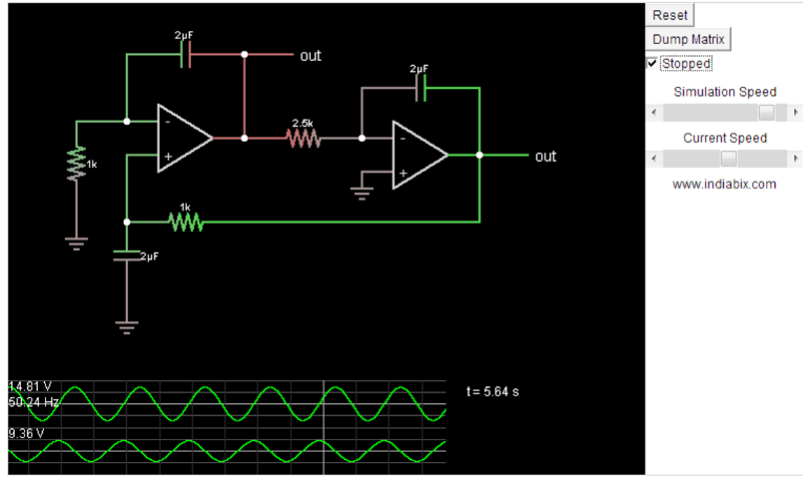
Pure sine wave inverter circuit diagram pdf efficient, inexpensive inverter with a pure sine wave output. The choice of the voltage to be used to power the inverter ranging from 12v to 48v depends on kva you are designing. For any setup, a 12v relay is to be use. Op amp 1 generates a 50 hz sine wave as the reference signal.
About press copyright contact us creators advertise developers terms privacy policy & safety how youtube works test new features press copyright contact us creators.
Op amp 2 as an inverter. To do so, you'll need the following: Here is 600 watt inverter pwm driver board electrical schematics and pcb screenshot: Block diagram of sine wave circuit is given below:
Learn more about different types of inverter here.
Pure sine wave inverter | code | schematics | pcb design | 5kwfor project file contact(send a mail): The icl7660 or max1044 can be selected. Pure sine wave inverter with led and lcd. Modified sine wave is easier to design than pure sine wave type and cost effective too, this type of inverter can support most ac loads but on some inductive loads like motors, fans, we can hear (humming) buzzing noise from its coil winding and also heats a bit more than pure sine wave.
230v, 50hz, 1.5kva, full bridge pure sine wave inverter circuit using sinusoidal pulse width modulation.
Kalian bisa merakit inverter dengan mudah dan murah dengan menggunakan design pcb yang saya buat ini. 3 high power sg3525 pure sinewave inverter circuits. 800va pure sine wave inverter’s reference design sanjay dixit, ambreesh tripathi, vikas chola, and ankur verma abstract this application note describes the design principles and the circuit operation of the 800va pure sine wave inverter. I have not used the opt coupler circuit instead i have used ir 2112 mosfet driver integrated circuit because in my country ir 2110 mosfet driver integrated.
Pure sine wave inverter pcb schematic and components name.
These pure sine wave inverters are very expensive, where the modified square wave inverters are inexpensive. The post details comprehensively regarding how to build a pure sinewave inverter circuit using microcontroller circuit with pic16f72. Experiment, if a pair of 190n08, totem part can be omitted, directly. First with a double voltage module voltage for the op amp power supply.
Make this 1kva (1000 watts) pure sine wave inverter circuit.
Sine wave inverter circuit using pic16f72. Utilizing pwm and analog components, the utilizing pwm and analog components, the output will be a clean sinusoid, with very little switching noise, combined with the inexpensive the microcare pure sine wave inverters deliver true clean sine wave output […] Eeengineers may 14, 2016 pure sine wave inverter , 2 comments. A modified sine wave can be seen as more of a square wave than a sine wave;