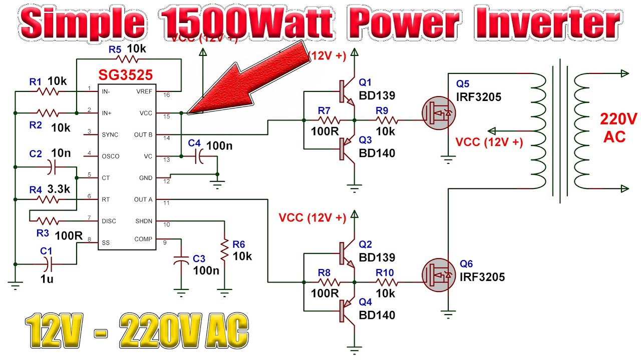
Transistor q1 is an inverting transistor to give a 180º phase shift. 1000w 12v dc home power inverter circuit board design. Please careful with this circuit.
100Winvertercircuit
For higher voltage inverters this supply must be appropriately stepped down to 12v for.
To get 750 watts of power from the inverter you need to add in parallel 2 of q7 and 2 of q8 to the original.
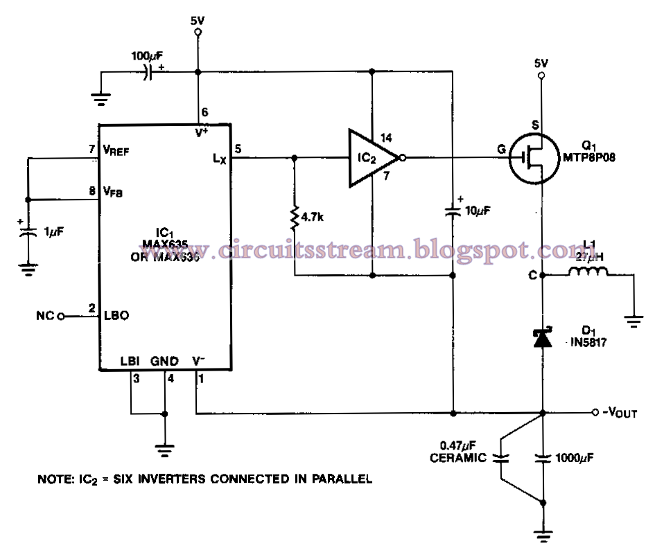
This is based on the mosfet3205. Variation of duty cycle in the pwm signal to provide a dc voltage across the load in a specific pattern will appear to the load as an ac signal, or can. The dc alteration to an ac can be attained by stored energy within the dc source like the battery Simple inverter circuit using arduino.
There are many basic electrical circuits for the power devices, a transformer, and switching devices.
The rfp50n06 fets are rated at 50 amps and 60 volts. In other words, it’s the device that changes dc (direct current) to ac (alternating current). Well as circuits for drive power supply and power losses in semiconductor devices. 1> the schematic circuit design is for a 250 watt output, while the pics are of my 1500 watts inverter that i built, to increase the power of the circuit you have to add more of the q7 and q8 transistors in parallel, each pair you add will increase your power by 250 watts, ex:
Circuit diagram of 3000 watt power inverter 12v dc to 230v ac.
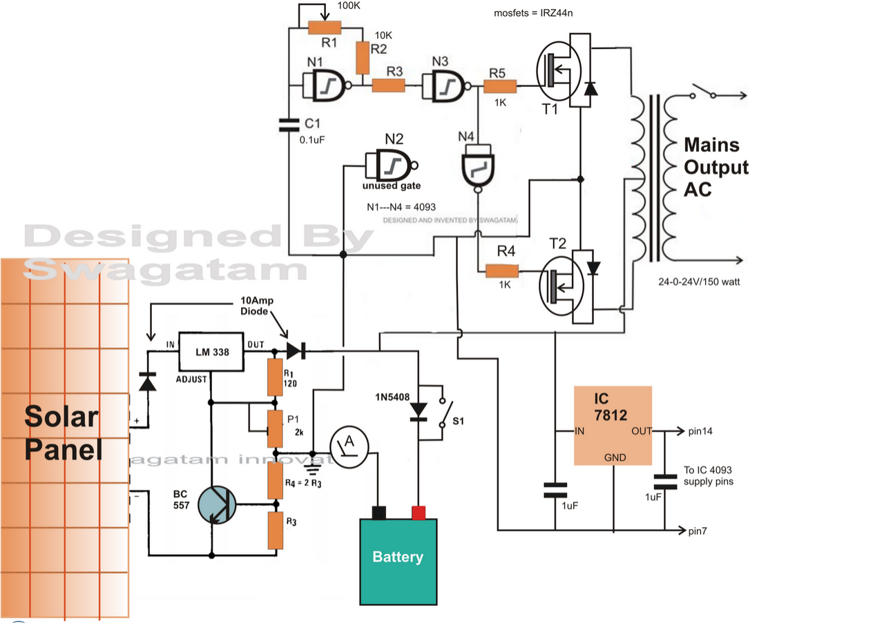
A power inverter circuit is a circuit that converts dc power to ac power. In general, lower power will offer easier successful, can do both experiments there is a certain practicality. Heatsink is required for cooling the mosfets. The vcc, and vss supply pins of the ic are not shown in the inverter diagrams, these must be appropriately connected with the 12v battery supply, for 12v inverters.
The inverter capable to handle loads up to 1000w, it’s depended on your power inverter transformer.
It can convert a 12vdc to 230vac 50hz/ 220vac 50hz/ 110vac 60hz output as your country. The inverter is an electronic device used to convert direct current (dc) into alternating current (ac). It is necessary to connect a fuse with the power line and always a load have to connected while power is being applied. In electronic power converters and motors, pwm is used extensively as a means of powering alternating current (ac) devices with an available direct current (dc) source or for advanced dc/ac conversion.
As several inverter designs have already been published on the web, the goal here was to make the design easily accessible to others by using familiar and easily sourced components available to novices and.
Next, power mosfet circuits are hight watts and easiest. This power inverter is designed for 12v dc, but also can be connected to 24v dc, my goal is 800 watt, strive to 1000 watt pure sine wave output. This is the circuit diagram of 2000w high power inverter circuit. Pinout diagrams for the ic 4093 and ic 4049.
Use 24v dc supply for operation and connect 24v 5a or more than 5a transformer.
A power inverter, inverter or invertor is a power electronic device or circuitry that changes direct current to alternating current. We are going to build a power inverter that takes its input power from a 12v battery, and outputs a 110v/230v ac current. This is the power inverter circuit based mosfet rfp50n06. This is the circuit diagram of high power 1250va digital inverter with charger.
The alternating current is a current that consistently changes its magnitude with respect to time.
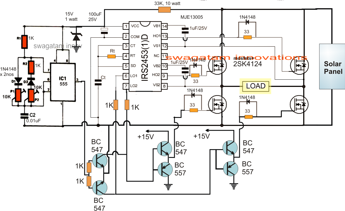
The control circuit, signal gathering circuit, and the switching tube drive circuit of solar on grid inverters need different adaptive power supplies. You can construct this circuit of a simple inverter at a cheap. It can be used as inverters for home needs to enable light loads (electric bulb, cfl, etc) at the time of electricity failure. The resulting ac frequency obtained depends on the particular device employed.
Circuit diagram | 3000 watt power inverter 12v dc to 230v ac.
This simple low power dc to ac inverter (dc to ac converter) circuit converts 12v dc to 230v or 110v ac.by doing simple modification you can also convert 6v dc to 230v ac or 110v ac. To begin with, you see transistors circuits are so easy. This 1000 watt power inverter circuit diagram based on mosfet rf50n06.if you want more power then add additional mosfet paralleled at rf50n06.this mosfets are 60 volts and 50 amps as rated. The input voltage, output voltage and.
Image of the pcb layout of this high power inverter circuit diagram is given.
1000w power inverter circuit diagram: Here is the circuit schematic: This simple inverter is constructed around an arduino board which gives very stable frequency of 50hz at 50% duty cycle. Square wave voltage with duty cycle 25% for 230 volt rms (modified sine)
Thus an independent power supply should be provided for powering these circuits.
The 50hz oscillator is provided by the 555 timer. You can learn how it works in a simple circuit. 12v dc to 220v ac inverter circuit pcb basic schematic for diagram the 2 wind power 100w switching transformerless simplified 240v electronic supply 5w solar 60w 230v voltage converter transformer less grid tie page 3 china 1000w simple 120v pure sine wave how build a projects. This current flows only in one direction.
Inverters do the opposite of converters which were originally large electromechanical devices converting ac to dc.
The circuit is outlined in the block diagram below. The output terminals of the inverter and the tweezers were scarred. You can make the ac power be any level that you want and to any frequency that you want. Arduino enthusiasts must try this inverter as this is the simplest possible inverter which.