The spwm accuracy of eg8010 was not high enough waveform, so the inverter output was not good enough as pure sine wave. Heatsink is required for cooling the mosfets. Three phase inverters require microcontroller design where the timings of the all three phases need to be precisely timed and executed.
Inverter Circuit 3000W Power Inverter Circuit
China 1000w power inverter dc 12v to ac 220v circuit diagram solar.
The breadboard circuit of the circuit above is shown below.
You do not have it now. This simple low power dc to ac inverter (dc to ac converter) circuit converts 12v dc to 230v or 110v ac.by doing simple modification you can also convert 6v dc to 230v ac or 110v ac. It is necessary to connect a fuse with the power line and always a load have to connected while power is being applied. This basic inverter circuit can handle up to 1000watts supply depends the t1, t2 and transformer used.
The power inverter circuit that we will build with a power transformer along with a few simple components is shown below.
Use 24v dc supply for operation and connect 24v 5a or more than 5a transformer. It is hard to find equipment. Power inverter design, circuit, diagrams here is the circuit diagram and pcb design for relatively low cost diy bass guitar preamp pedal uses fet k117 or equivalent. You may acquire a variable range of output pulse at pin 10 q and pin 11 q’ pins by adjusting the value of.
Also, another main application of inverters is on the power consumption and grid.
R1 = 220k pot, needs to be set for acquiring the desired frequency output. There is a bit difficult to build this kind circuit project, it’s require a good knowledge in electronics. The internet is flooded with single phase inverter circuit diagrams, but there are only few circuit diagrams of 3 phase inverter out there, a simplest possible 3 phase inverter is described here. In other words, this type of inverter has unique functions made for photovoltaic arrays.
This is the circuit diagram of 2000w high power inverter circuit.
Circuit diagram | 3000 watt power inverter 12v dc to 230v ac. The circuit will convert 12v dc to 120v ac. Few days ago, gohz made a 24v 2000w power inverter in home, sharing some design schematics and circuit diagrams. Please careful with this circuit.
Inverter wiring correct inverter wiring in a battery based pv system abstract.
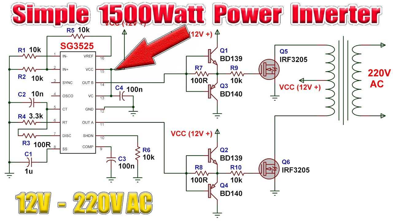
The cd 4047 ic is configured in this 12 volt to 220 volt inverter with the aid of several components like the potentiometer, capacitors, and resistors. There are many basic electrical circuits for the power devices, a transformer, and switching devices. This 1000 watt power inverter circuit diagram based on mosfet rf50n06.if you want more power then add additional mosfet paralleled at rf50n06.this mosfets are 60 volts and 50 amps as rated. The inverter capable to handle loads up to 1000w, it’s depended on your power inverter transformer.
This is the power inverter circuit based mosfet rfp50n06.
This preamp has several features for the bass guitar instrumentâ such as The purpose of a dc/ac power inverter is typically to take dc power supplied by a battery, such as a 12 volt car battery, and transform it into a 120 volt ac power source operating at 60 hz, emulating the power available at an ordinary household electrical outlet. 12v dc to 220v ac inverter. If you think that this circuit is not good enough.
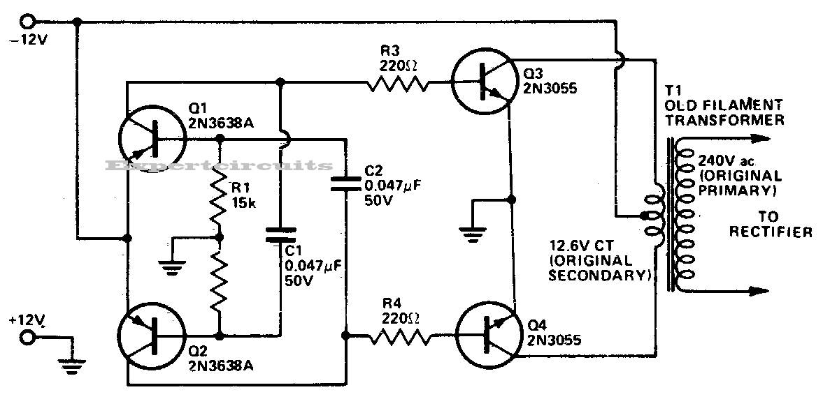
Power inverter 60w 12v dc to 230v ac using 2n3055 electronic schematic diagram.
With this kind of an illustrative guidebook, you’ll have the ability to troubleshoot, prevent, and total your tasks without difficulty. This is the circuit diagram of high power 1250va digital inverter with charger. Circuit diagram of 3000 watt power inverter 12v dc to 230v ac. You can construct this circuit of a simple inverter at a cheap.
Square wave voltage with duty cycle 25% for 230 volt rms (modified sine)
The dead zone time was a bit. This is based on the mosfet3205. It can be used as inverters for home needs to enable light loads (electric bulb, cfl, etc) at the time of electricity failure. The inverter is an electronic device used to convert direct current (dc) into alternating current (ac).
R2, r3, r4, r5 = 1k, t1, t2 = irf540;
Pins 10 and 11 are used to collect the output. The dc alteration to an ac can be attained by stored energy within the dc source like the battery. Also 500w inverter circuit for you. Image of the pcb layout of this high power inverter circuit diagram is given.
They can convert 12vdc from battery to 220vac or 120vac to apply small light bulbs or lamps max 10 watts.
You can use a variety of voltages to power the circuit. 1000w power inverter circuit diagram: Small power inverter tags circuit schematic diagram. The alternating current is a current that consistently changes its magnitude with respect to time.
In the two circuit diagram below, just use 2 transistor, 2 resistors, and one transformer only.
Pv solar inverter circuit diagram inverter circuit gives alternating current ac output from battery power source but the battery requires constant dc supply to get charge so the every inverter circuit contains rectifier and battery charger segment. This circuit is envisaged frequency in 300hz. The first thing is powering the circuit. The purpose is to reduce the inverter transformer size and weight, output is square wave.
This is a kind of excellent performance power inverter for home circuit diagram, materials are easy to get, and the output power can reach 150w.
Parts list for the above explained 150 watt inverter circuit diagram: The inverter can be used in home lighting, electronic ballasts for fluorescent lamps, and household. The following diagram is the basic design diagram of inverter circuit. This current flows only in one direction.
The rfp50n06 fets are rated at 50 amps and 60 volts.
C1 = 0.01uf, c3 = 0.1uf;