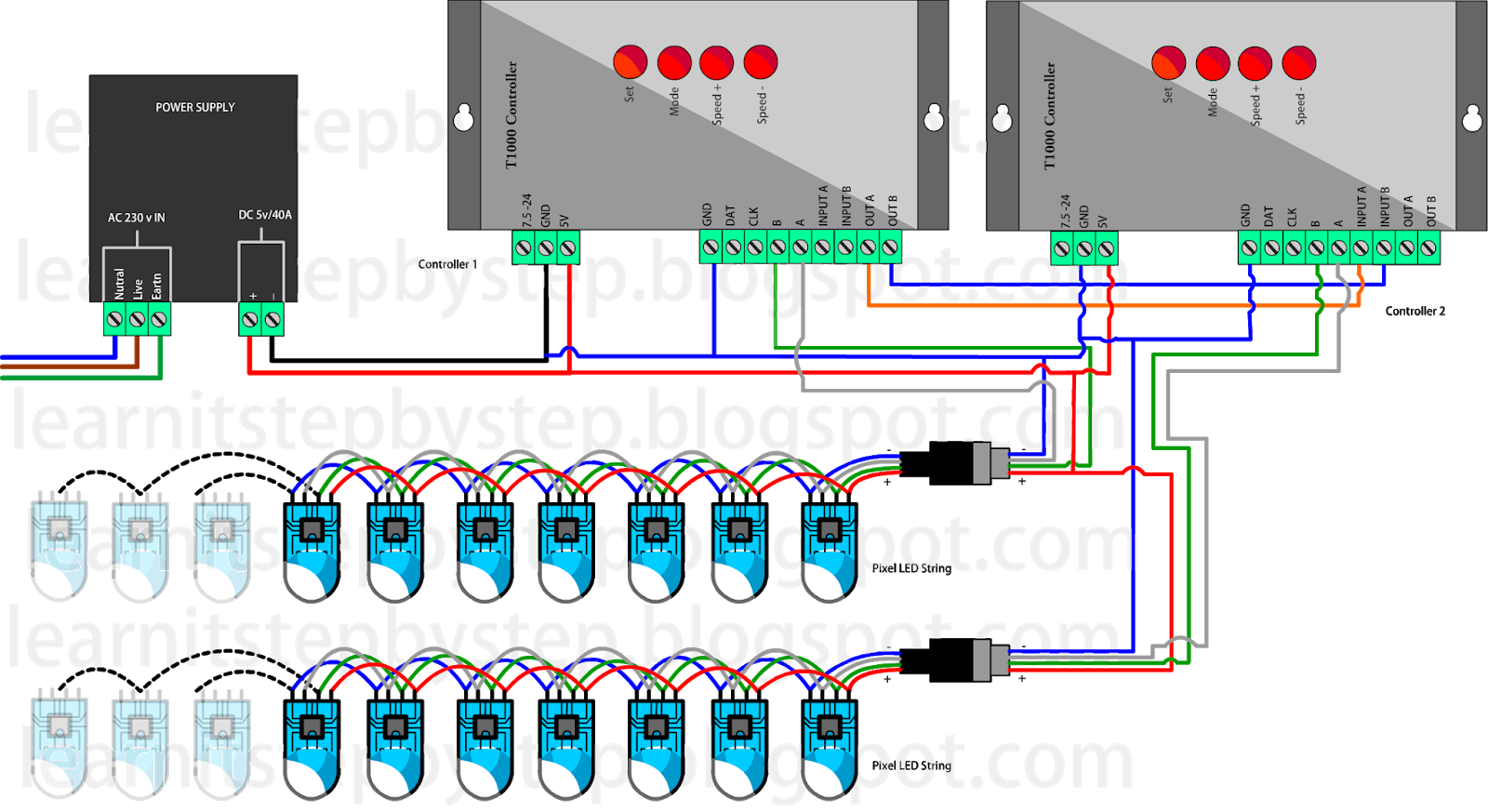
The way that the schematic symbol of the led maps to the physical led is shown in the diagram below: How to do ws2811 wiring diagram? I have been reading up on pixels for about 2 years now.
Plan Wiring NeoPixel Painter Adafruit Learning System
I went to school for electrical engineering and currently work in automotive electronics field.
This is a proprietary connector used by diyledexpress.
Connecting the wires in the wrong polarity (wrong order) to a controller can destroy the pixel string and or the controller so it is very important that the connections be made correctly. Pixel led controller connection ka diagram ke bare main jane*buy productpixel t8000 ac : Both the spi controller and the light strips need to be powered separately. 4 channels per dot rgb:
Learn how to use arduino to control neopixel rgb led strip, how to control color and brightness of each individual led on the strip, how to program arduino step by step.
The led strip made by the adafruit company to avoid the pins issue and complex circuitry. The led is a very common 3 led (red, green, blue) package, in one 5mm x 5mm case. Where there is a voltage drop, a separate power supply is required. These look to be compatible with the lor style connectors, but they are just a tad bit different in thread size.
Identify the “input” end of your neopixel strip, pixel (s) or other device.
3 channels per dot dmx/rdm: A tutorial to create a cheap (approx. I am looking for some wiring diagrams of parts of your displays. By iot | july 1, 2015.
How to build an rgb led circuit with arduino layman s module use in driving control the scientific diagram l6 leds physical computing guide codrey electronics programino ide color picker software for structure schematic working its types a common cathode driver smartphone operated.
This is a graphic illustration of how 5 volt pixel leds are wired. It is an onboard smart digital port lock and signal reshaping inference drive circuit that effectively ensures the color of the pixel point light is high and consistent. On some, there will be a solder pad labeled “din” or “di” (data input). The data wire needs a resistor of 220 to 560 ohms inserted between the strip and the micro controller.
The second to achieve long led light strips installation is to connect multiple addressable led strip lights in series.
The connection goes right now; The cathode is marked on the rim of the led body with a flat area shown in the diagram. We can control a ws2811 rgb led. Neopixel led is a strip of leds with rgb combinations.
Connection diagram for the neopixel addressable leds using arduino is shown in fig.
This article introduces you to pixel tape, and explains some of the basics you need to get started. The data input can originate from any digital pin on the arduino, but all the example code is set up for digital pin 6 by. The strip uses a 5050 rgb leds the whole leds to connect with the use of an ic ws2812/sk6812. Simplify your setup and get on track with a custom made show wiring diagram.
Each led consume around 60ma so make sure your power supply can source enough current for all the led.
Send us your display layout and a list of controllers you expect to use. The whole strip has a total of max 144 leds in a series. My previous display was over 100,000 led's (static). The second led pixel grabs rgb bit sequence, displays it, and so on, until the end of the chain is reached.
It is a bit smaller than the other three but shares the most common characteristics in that it has a square notch and the nut is on the male side.
Note that you do not have to connect the pixel strip to a pwm pin on the arduino. What’s more, the female port assists with giving the information sign to the following led strips. Connection to any data pin is fine. Another way to tell which lead is the anode and which is the cathode is to look at the two plates at the end.
This diagram will instruct you where each prop is plugged so you can quickly hook up your show.
The ws2812 is a smart led light source family which integrates the control circuit and the rgb chip into a 5050 part package. No matter how confusing it is, and we will design a controller location map. Gnd rj45 plug pin 2: Let us assume you are using a 5 led rbg strip neo pixel with arduino, and then in that case the leds can be directly powered by the 5v pin of arduino since they can source upto 500ma.
A ws is the same package but with an additional ws led driver ic on board.
The length of the cable between the pixel distributor and the first lamp or lamp holder shall Led pixel tape, on the other hand, allow you to control each led individually via a special control protocol. Others will have an arrow showing the direction that data moves. The male port is utilized to impart the control information sign to the leds.
On the physical led, the longer lead (or leg) of the led is the anode.
The pwm pulses are varied to produce multiple colours with the combination of rgb leds. Most pixel strings use either three or four wires to connect to the pixel controller.


