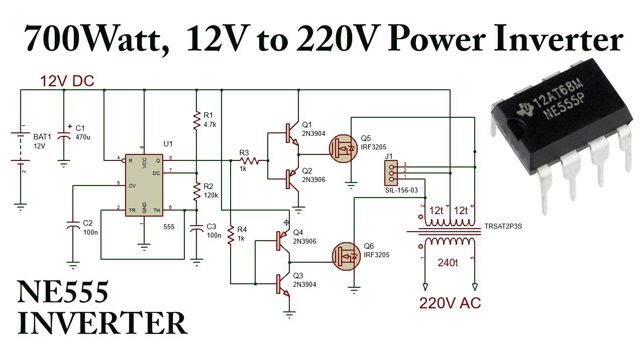
The transformer steps up the voltage to 220v ac. This circuit was created by a member of the community and has no affiliation to the circuit diagram project. Many drawbacks and flaws were detected while assessing the above circuit details.
Ne555 Inverter Circuit Circuit Diagram Images
Here we discuss about the single phase sine wave inverter, i/p voltage = 12v dc.
Ne555 is an ic which is widely used in timers and control circuits.
This inverter circuit uses two ic ne555 and sn74ls112 and 10 2n3055 transistor with. Output voltage range from 7.5v to 35v dc with 60ma current. In this diy tutorial, we are demonstrating the project of a 7 segment counter using a. The first inverter comprises c1, c2, d1 and d2.
With irf1404 as the mosfets, the inverter would be able to generate anywher around 300 to 5000 watts of pure sine wave output.
But how small it may seem to be you’ll not believe that it. Thus, i make a simple 555 ics tester circuit. Preferred components for the serious experimenter. The second inverter, comprising c4, c5, d3 and d4, is also driven from the output of ic1.
There are many types of inverter such as single phase inverter, three phase inverter, amplifier type sine wave inverter, saturated type square wave inverter, transistorised inverter & thyristorised inverter.
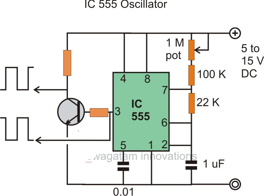
Components ne555, bc547, bc557, capacitor The above circuit may be further enhanced with an automatic load correction feature. But normal multimeter cannot check it. A collection of 555 circuits using the 555 timer as an astable oscillator with different duty cycles.
Is it good or bad?
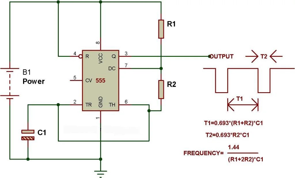
We have seen in the last few tutorials that the 555 timer can be configured with externally connected components as multivibrators, oscillators and timers, with timing intervals ranging from a few microseconds to many hours. Ne555 is an 8pin ic that is used mostly. This tutorial teaches you about how to diy a ne555 circuit to generate sine wave. The circuit is implemented on proteus.
Voltage inverter circuit using ic ne555.
And these oscillations are switched via transistor 2sc4029 to a transformer. The proposed boost converter circuit can operate from 5v to 15v and can output a variable voltage up to 40v. It is operated in 3 modes astable, monostable, bistable. The finalized circuit (hopefully) is presented below.
The ic possesses an oscillation frequency ranging from 670 to 680 hz.
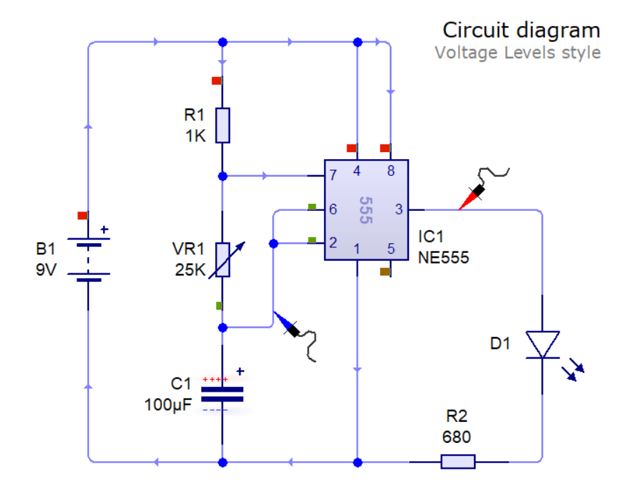
Learn by doing is the best. Which is tested correctly and faster. Here is the simple inverter circuit diagram using 555 timer ic. Ne555 ic is used as a clock generator, you can achieve variable frequency as well as variable duty cycle according to your application just by playing with resistors and capacitors.
That is when output is high d2 will glow & when output is low d3 will glow.
It has a large range of operating voltages ranging from +5v to +18v. The ic 555 can handle it like piece of cake. Hi, in this video tutorial i'll show you how to make a high voltage pure sine wave inverter with the 555 timer ic. The output of the ne555 is connected to two voltage inverters.
Use a 12v battery and battery charger circuit for this project.
4 months ago by shagufta shahjahan. A 555 timer ic serves as the core of this 6v to 12v converter circuit. 7 segment counter using ne555 and cd4026. It's a flyback driver circuit with an lc r.
Inverter is also a timing based circuit whose frequency and duty cycle are important parameter.
This affordable diy kits is very helpful for you to understand the how can the capacitors work with resistors to control the charging and discharging time that to generate a sine wave.if you are a newbie in electronics please refer to resistor knowledge and capacitor knowledge to learn more. 12v to 220v inverter using ne555 by krystof 9352 details; Boost converter circuit using ic 555. A circuit for independent testing this ic is given here.
O/p voltage = 230v ac.
Simple ne555 ic tester circuit diagram. When the push button switch s1 is pressed the leds d1 & d2 will flash alternatively. Here the ne555 is wired as an astable multivibrator. The astable multivibrator mode operation of 555 timers is utilized here for ac oscillations.