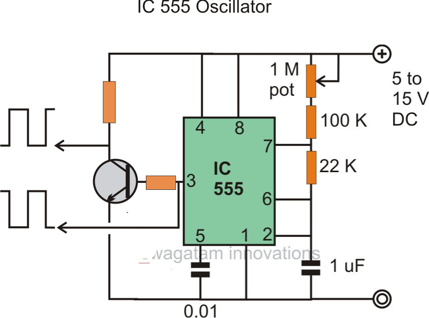
The 555 timer ic is an integrated chip used in a variety of timer, pulse generation, and oscillator applications. Many drawbacks and flaws were detected while assessing the above circuit details. The frequency of astable multivibrator is given by, choose c = 10µf.
Signal Generator and Inverter Using NE555 Timers Full
There are many inverter circuits using ic based oscillators around the internet, but none can beat the popularity of ic 555 which has tons and tons of applications in timing based circuits.
Learn by doing is the best.
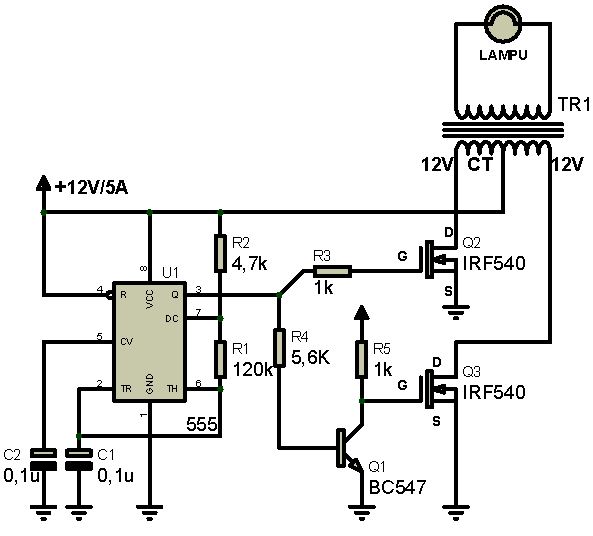
The diagram above shows the entire design of the proposed spwm inverter circuit using ic 555, where the center ic 555 and the associated bjt/mosfet stages forms a basic square wave inverter circuit. Two other packages of the timer ics are available which are 556 and 558. 12v to 220v inverter using ne555 by krystof 9352 details; A 555 timer ic serves as the core of this 6v to 12v converter circuit.
Circuit diagram of signal generator.
Where ve = r2 / (r1 + r2) * vcc + vbe. Inverter is also a timing based circuit whose frequency and duty cycle are important. Here the resistor of previ ous circuits is replaced by a pnp transistor that produces a constant charging current. In the circuit above is completely circuit diagram of this project.
The signal generator produces forward and inverted signals through ic2 and ic3, respectively.
4 months ago by shagufta shahjahan. This affordable diy kits is very helpful for you to understand the how can the capacitors work with resistors to control the charging and discharging time that to generate a sine wave.if you are a newbie in electronics please refer to resistor knowledge and capacitor knowledge to learn more. This circuit produces a sound like factory siren. This inverter circuit uses two ic ne555 and sn74ls112 and 10 2n3055 transistor with.
Voltage inverter using a 555 schematic circuit diagram.
Which is tested correctly and faster. Use a 12v battery along with a battery charger circuit to power this dc to ac inverter. Is it good or bad? The circuit of a ramp generator using timer 555 is shown in figure.
Simple ne555 ic tester circuit diagram.
Thus, i make a simple 555 ics tester circuit. Circuits into the ever increasing ranks of timer users. It applies a 555 timer ic which is utilized as an astable multivibrator of a center frequency of about 300hz. You may change the 10k resistor with variable resistor.
The above circuit may be further enhanced with an automatic load correction feature.
Transformerless 12v 24v converter with ne555 timer integral schematic circuit diagram. For a 555 timer stable multivibrator designed to oscillate at 50hz, the line frequency can be calculated easily. The circuit diagram of the signal generator is shown in fig. A lot of electronic circuits using ne555 timer ic are already published here and this is just another one.here is the circuit diagram of a police siren based on ne55 timer ic.
Hello , i'm new around here , and i was just watching some 555 circuits when i found out about this.
To understand the basic concept of the timer let’ s first examine. Charging current produced by pnp constant current source is. This is the circuit diagram of a 300w simple inverter. But normal multimeter cannot check it.
This tutorial teaches you about how to diy a ne555 circuit to generate sine wave.
This circuit shows how it is possible to use a trusty old ne555 timer ic and a bit of external circuitry to create a voltage inverter and doubler. Hi, in this video tutorial i'll show you how to make a high voltage pure sine wave inverter with the 555 timer ic. It's a flyback driver circuit with an lc r. The input voltage to be doubled is fed in at connector k1.
7 segment counter using ne555 and cd4026.
In many circuits we need to generate an internal adjustable voltage. The sound frequency can be adjusted by varying the 10k resistor. In many circuits, we need to generate an internal adjustable voltage. Our aim is to chop these 50hz square waves into the required spwm waveform using an opamp based circuit.
This circuit was created by a member of the community and has no affiliation to the circuit diagram project.
The ic possesses an oscillation frequency ranging from 670 to 680 hz. Design of a 12v to 220v 555 timer ic inverter circuit schematic. When a trigger starts the monostable. The input voltage to be doubled is fed in at connector k1.
The ic timer ne 555 used as astable multivibrator operating at about 1khz and produces a sound when switched on.
It is built around two ne555 timers (ic2 and ic3), an led (led3), seven bat42 schottky diodes (d3 through d9) and a few other components. This circuit shows how it is possible to use a trusty old ne555 timer ic and a bit of external circuitry to create a voltage inverter and doubler. With irf1404 as the mosfets, the inverter would be able to generate anywher around 300 to 5000 watts of pure sine wave output. In this diy tutorial, we are demonstrating the project of a 7 segment counter using a.
Full circuit diagram of ic 555 based inverter:
The 556 timer ic has 2 timing circuits “dual timer”, while the 558 timer ic has a total of 4. Here the circuit diagram of electronic siren based ne555. The frequency is controlled by the pin 5 of the ic.