To determine this, connect the meter movement, a potentiometer, battery, and digital ammeter in series. Schematic diagram dt9205a digital multimeter: Digital voltmeter is a voltage sensitive device.it measures ac or dc voltage and displays the value directly in numeric form instead of pointer deflection.
Schema multimetre digital
For that reason, requires that the transient withstand capability of the equipment is made known to the user.
Multimeter is a measuring instrument.
So the additional block to the diagram of figure, to act as a panel meter to measure alternating voltage is a.c to d.c. A multimeter can be used to measure electrical functions such as voltage, current, resistance, continuity and some are able to measure electrical frequency. In general, dmms have a minimum of five typical functions. In addition it must have a provision for measurement of resistance also.
Actually it is a voltage source.it uses digital, analog or both techniques to generate a rectangular pulse.
It is also called electronic multimeter or voltage ohm meter (vom). So, it can be used to measure dc. Digital panel meter block diagram. There are two main types of multimeters.
It is so versatile available function.
They are dc voltage, ac voltage, dc current, ac current, and resistance. Its characteristic equation is given by ohms law. Explanation of various blocks input signal: It can be used to measure voltage, current and resistance.
The block diagrams for measuring steady voltage, and alternating voltage are shown above :
Working of this digital voltmeter circuit is very simple. While specifications vary, most dmms can be described with block diagrams similar to figure 1. Interpret this ac motor control circuit diagram explaining the meaning of each symbol. The block diagram of a simple digital voltmeter is shown in the figure.
It is also known as the voltmeter or ohm meter or volt ohm meter.
Some models also provide transistor test function, signal output or performing continuity test. Let us have a look at its working and specification one by one. I'm looking for the internal circuit diagram of dt830x (or dt830d). The 8051 microcontroller, a voltage sensor module, and an adc ic.
The combination of a resistor in series with pmmc galvanometer is a dc voltmeter.
Staircase ramp digital voltmeter (also called digital ramp) •the most simple a/d •slow conversion and conversion time depends on the magnitude of input signal. To produce an accurate output on the lcd, the input voltage should be dc. If you use ac voltage as an input, the lcd will display continuous running figures as the ac varies. Then only it becomes the digital avo meter.
It is basically the signal i.e.
Adc inside the ic is integrating converter or dual type analog to digital converter. Apart from these, a digital multimeter can also measure temperature, frequency, capacitance, continuity, transistor gains etc. The voltage intended to measure is primarily converted into digital equivalent using dual slope type analog to digital converter inside the ic7107. For example, measure dc voltage, acv, dc amp meter, ac amp meter and as the ohms meter, etc.
I am showing you a digital multimeter circuit using icl7107.
Analog multimeter shown in the figure is cheap but difficult for beginners to read accurately. Most modern multimeters are digital. A digital multimeter is one that is capable of measuring voltage, current, of alternating current circuits as well as direct current circuits. Most have four digits, the first of which can often only.
Its block diagram is shown below in the figure.
Display the display on a dmm is normally easy to see and read. Digital multimeter is a test equipment which offers several electronic measurement task in one tool. The led digital voltmeter working with circuit diagram can be easily understood with this simple overview description below. It's a simple multimeter capable of accomplishing varied measurements.
Digital voltmeter using 8051 microcontroller.
The standard and basic measurements performed by multimeter are the measurements of amps, volts, and ohms. Then, this value is decoded and displayed on led based electronic display. First, you need to determine the characteristics of your meter movement. There exist many factors that affect the measurement accuracy of a digital voltmeter(dvm).
The standard measurements that are performed by a dmm are current, voltage and resistance.
A multimeter, shown in figure 1, is a device used to measure two or more electrical quantities. Digital multimeter as voltmeter, ammeter and digital ohmmeter. Circuit diagram and working explanation: • when using this multimeter, the user must observe all normal safety rules concerning:
Dvm is an acronym for digital voltmeter.dvm was first invented in 1954 by andrew kay.
D/a output time v ax clock period v in t (2n 1) clock period c,max = − × clock comp. The above circuit looks like a multi range dc voltmeter. The block diagram of 7107 and that of. The part of the circuit diagram of multimeter, which can be used to measure dc voltage is shown in below figure.
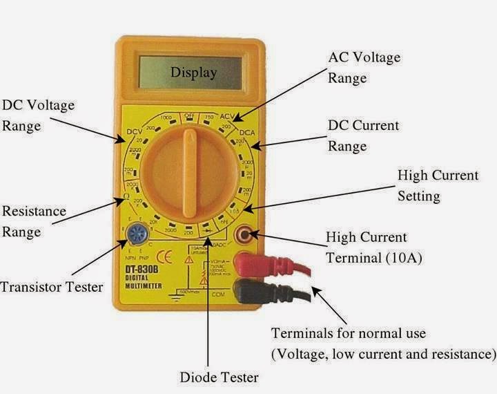
Digital multimeter showing the controls & connections.
Dt9205a digital multimeter circuit diagram : In digital multimeter, we can incorporate many types of meters like ohmmeter, ammeter, a voltmeter for the measurement of electrical parameters. The input voltage ranges from 0 to 25 volts in this project. The function of the meter can be changed by switching the dial.
Digital multimeters convert analog signals to digital information.
The width and frequency of the rectangular pulse is controlled by the digital. Internal adc of this ic reads the voltage that to be measured and compare it with an internal reference voltage and converts that into the digital equivalent. The main connection on a typical digital multimeter are given in the image and description below, but obviously the exact layout and capabilities will be dependent upon the particular test instrument in use. An analog meter (figure a) moves a needle along a scale.
The 200 mv module is shown only as a single block.
A digital multimeter (dmm) is a measuring instrument used to measure various electrical quantities. Digital multimeter block diagram explanation. Dt9205a based digital multimeter schematic: Digital multimeter circuit using icl7107.