Stock image by robertomm 3 / 42 technician examining air conditioner stock photo by andreypopov 2 / 44 analog multimeter pictures by dengess 1 / 65 multimeter stock photographs by connect 0 / 29 electrician checking socket stock images by amaviael 2 / 10 digital multimeter stock images by alexciopata 2 / 206 measuring instruments and electrical. Electrician engineer work tester measuring voltage and current of power electric line in electical cabinet control. Below are composite images of clamp meters’ display, dial, and the buttons.
Digital Multimeter Working Principle Electrical Academia
No single model contains all these functions.
Up to 10% cash back find the perfect multimeter diagram stock photo.
If you want to test a dc circuit, switch the setting on your multimeter to vdc or dcv. As shown in the block diagram, in a typical digital multimeter the input signal i.e ac or dc voltage, current, resistance, temperature, or any other parameter is converted to dc voltage within the range of the adc. This is a composite image and not an actual dial. Voltmeter is useful in that it can give a warning of many electrical problems and can show many problems faster than an ammeter.
Browse 1,572 multimeter stock photos and images available, or search for digital multimeter or electrical multimeter to find more great stock photos and pictures.
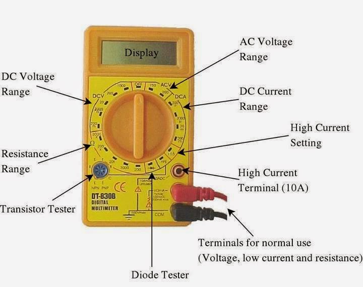
This multimeter has three different ports labeled 10a, com (which stands for common), and mavω. On many models, some function icons are displayed in yellow. Multimeter, electrician tools on black background, digital. Multitester tool on electronic scheme diagram.
• the function switch dial is turned to select the meter’s function.
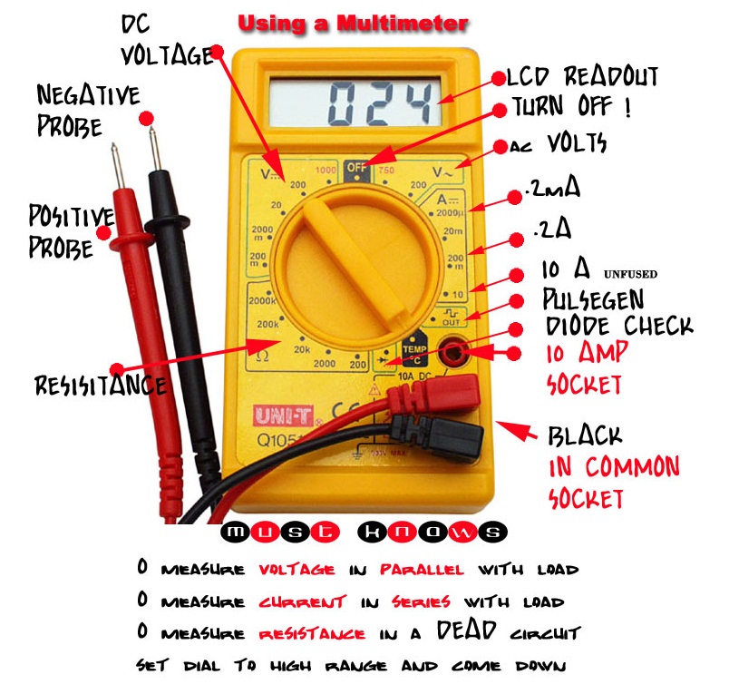
It shows a variety of functions found on multiple fluke digital multimeter dials. Below the digital readout is a black dial, called the function switch. The basic digital multimeter will typically have a switch, display, and the connections for the test probes. Browse 303 voltmeter stock photos and images available, or search for ammeter or volt meter to find more great stock photos and pictures.
The above circuit looks like a multi range dc voltmeter.
On an ac circuit, for example,v stands for voltage, while a squiggly line indicates the alternating current. Digital multimeter layout • the top portion of the meter contains the digital readout area which displays the measurement value. To determine this, connect the meter movement, a potentiometer, battery, and digital ammeter in series. Huge collection, amazing choice, 100+ million high quality, affordable.
On digital ones, look for similar tags next to a number.
So, it can be used to measure dc voltages up to certain value. Turn the meter on if it has a separate power switch. Open and save your projects and export to image or pdf. On analog multimeters, there’s a scale on the display labeled as ohms, resistance or the ohm symbol (ω).
Episode 54 basic component faultfinding with a multimeter.
A multimeter is the tool to measure these three parameters. The diagrams aren’t specific to one clamp meter model, they illustrate the range of functions. When there is little resistance, there will be a great deal of continuity, and vice versa. Some feature the measurement of additional properties such as temperature and.
This setup is rated to measure current up to 10 amps.
Free editor to create online diagrams. The part of the circuit diagram of multimeter, which can be used to measure dc voltage is shown in below figure. Disconnect the battery’s ground cable before working on the voltmeter. On an analog multimeter, you’ll have different types of scales.
The first digital multimeter was introduced in the late.
Every fluke clamp meter offers a different combination of functions, but no matter which one you grab, you’ll need to know what the symbols and buttons mean as well as where they show up on the display screen. A multimeter is a measuring instrument that can measure multiple electrical properties. This indicates the digital multimeter’s yellow function button must be pressed. These are labeled “ac” or “dc” and have a v for “voltage.”
First, you need to determine the characteristics of your meter movement.
The combination of a resistor in series with pmmc galvanometer is a dc voltmeter. Working principle of digital multimeter. Set the multimeter to ohms or resistance. Multimeter in hands of electrician engineer in electrical cabinet.
When multimeter measures resistance in ohms, it can not measure continuity because resistance and continuity are opposites.
To read a multimeter on an ac system, you'll need to locate the numbers and symbols on your circuit system. Use our diagram editor to make flowcharts, uml diagrams, er diagrams, network diagrams, mockups, floorplans and many more. The main connection on a typical digital multimeter are given in the image and description below, but obviously the exact layout and capabilities will be dependent upon the particular test instrument in use.


..png)

