Working of this digital voltmeter circuit is very simple. An analog meter (figure a) moves a needle along a scale. Position and reposition the test till a dependable reading appears on the meter lcd.
Digital multimeter circuit using ICL7107
Schematic diagram dt9205a digital multimeter:
Measurements by using multimeter dc voltage measurement.
Vis terms of use, ethical policy, copyright And show pcb layout and the components as shown in figure 8. Digital multimeters are widely accepted worldwide as they have better accuracy levels and ranging from simple 3 ½ to 4 ½ digit handheld dmm to very special system dmm. If you want more the voltage range.
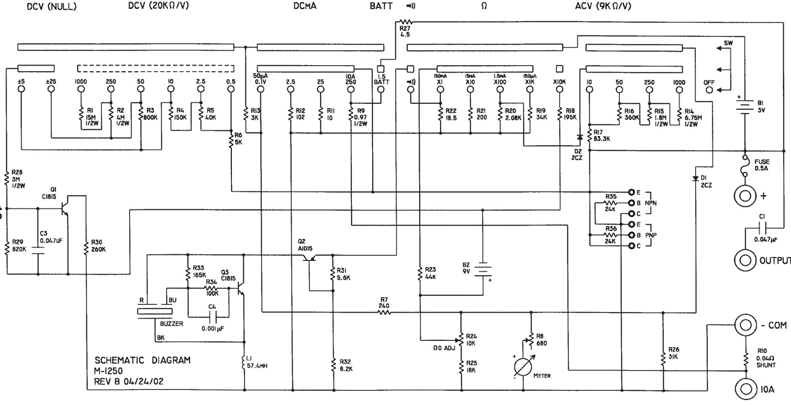
A multimeter can measure voltage, current, and resistance for which its galvanometer is converted to a voltmeter, ammeter, and ohmmeter with the help of suitable circuits incorporated in it.
Da output time v ax clock period v in t 2n 1 clock period cmax clock comp. Download scientific diagram circuit diagram of the digital multimeter dmm from publication. In addition it must have a provision for measurement of resistance also. It's a simple multimeter capable of accomplishing varied.
I have already explained components of circuit.
In figure 5 is the digital voltmeter circuit designed for general applications. Digital multimeter block diagram explanation. Proposed model of digital multimeter is preferable dueto their accuracy durability and extra features. First, you need to determine the characteristics of your meter movement.
2.5 volts, 10 volts, 50 volts, 250 volts, 500 volts, and 1000 volts.
Circuit diagram and working explanation: The circuit diagram for a direct coupled amplifier dc voltmeter using cascaded transistors is shown in figure. The function of the meter can be changed by switching the dial. Here is a full circuit that works perfectly.
The part of the circuit diagram of multimeter, which can be used to measure dc voltage is shown.
A balanced bridge dc amplifier and a pmmc meter. Start date feb 24, 2013; Im looking for the internal circuit diagram of dt830x or dt830d. Status not open for further replies.
Index 390 basic circuit diagram seekic com.
A transistor is a current controlled device so resistance is inserted in series with the transistor q 1 to select the voltage range. Dt9205a based digital multimeter schematic: A digital multimeter is one that is capable of measuring voltage, current, of alternating current circuits as well as direct current circuits. A deep dive into analog multimeters engineering360.
Suppose the meter operator chose to switch the meter into the “volt” function.
The circuit for reducing the voltage, the circuit consists of rx, ry, calculated as follows. These two channels are used to measure ac voltage and current. The resistor r1 and capacitor c1 are used to set the internal oscillator (clock) frequency at 48hz, clock rate at which there will be three readings per second. Yx 960tr analog multimeter sanwa ampere electronics.
Digital multimeter circuit diagram circuit diagram of digital multimeter is given.
To determine this, connect the meter movement, a potentiometer, battery, and digital ammeter in series. As the test continues the measurement will steady. Two analog to digital converter channels are used. Led digital voltmeter circuit diagram with ic7107 the voltage intended to measure is fed to the circuit through resistors and capacitors as shown in the figure.
1 of 2 go to page.
Pic microcontroller have built in adc’s. Which it requires the maximum range equal to 200mv. Figure 8 the pcb layout and components layout. Electronic multimeters it is one of the most versatile general purpose instruments capable of measuring dc and ac voltages as well as current and resistances.
Dt9205a digital multimeter circuit diagram :
Internal adc of this ic reads the voltage that to be measured and compare it with an internal reference voltage and converts that into the digital equivalent. This particular multimeter has several basic voltage measurement ranges: The part of the circuit diagram of multimeter, which can be. The galvanometer used in a multimeter has always its pointer resting at zero position on the extreme left end various measurements are made on a multimeter.
It can be used to measure voltage, current and resistance.
Sanwa yx 360tr analog multimeter online at best s in stan daraz pk. An attenuator is used in input stage to select voltage range. Apply the leads to the test circuit. Multimeter is a measuring instrument.
The digital multimeter is the most advanced measuring instrument that makes use of modern integrated circuits for making electrical measurements.
An attenuator in input stage to select the proper These adc convert analog value into digital number. Full a digital multimeter circuit diagram. The two ways to get 10mohm input impedance in mv range, in the first schematic the v range is used, but with a x10 amplifier electronically switched.
Adc inside the ic is integrating converter or dual type analog to digital converter.
Most modern multimeters are digital. Then only it becomes the digital avo meter. Feb 24, 2013 #1 i'm looking for the internal circuit diagram of dt830x (or dt830d). Analog multimeter shown in the figure is cheap but difficult for beginners to read accurately.
Multimeter design this is a look on how a typical modern multimeter is designed, it is not a look at any specific meter, but more the general ways the different ranges on a multimeter is made.
With the use of the voltage range extender unit at the top of the multimeter, voltages up to 5000 volts can be measured. While measuring ac voltage, variations may happen in the reading.