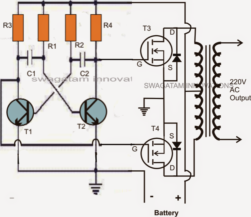
This is another 100 watt inverter circuit diagram. 1 shows single phase bridge inverter with resistive load. This circuit uses a multivibrator circuit running in astable mode to generate a free running square wave.
I'm Yahica Inverter Circuit Diagram Using Mosfet
A transistor multivibrator circuit basically is composed of two symmetrical half stages, here its formed by the left and the right hand side transistor stages which conduct in tandem or in simple words the left and the.
Sine wave inverter circuit description.
This is the power inverter circuit based mosfet rfp50n06. Simple low power inverter circuit | 12v dc to 230v or 110v ac | diagram using cd4047 and irfz44 power mosfet. Now you know how a basic inverter works. Simple mosfet inverter circuit diagram.
Find every electronics circuit diagram here, categorized electronic circuits and electronic projects with well explained operation and how to make it procedure and then new circuits every day, enjoy and discover electronics.
The transformer i use 2a current and 12v input at output power more than 100 watts. This is the circuit diagram of high power 500w inverter. Below is also component layout/pcb layout of this schematic diagram. A circuit symbol description of the two pairs of transistors from the data sheet is shown below in figure 1.
The inverters can be applied directly to the design of logic gates and other more complex digital circuits.
Referring to the figure, transistors t1 and t2 along with the other r1, r2, r3 r4, c1 and c2 together form a simple astable multivibrator (amv) circuit. On powering on the circuit using a 12v battery, a. The pcb layout of this circuit diagram is below. High side mosfet driver circuit tri state power diagram all gate isolated for pwm and igbt circuits 3 drivers what why por cheap in circuitlab use tc4420 simple h driving p channel project half bridge drive guidelines microchip technology discrete using single output n stepper motor switchcraft l6498 voltage low safe operation area 4 7 2 design.
Inverter circuit is one of the fundamental building blocks in digital circuit design (not to be confused with a power inverter).
We can achieve 220v ac at the output of just 12 volts. In circuit use irf540 mosfet. Bc548 / any npn transistor x 2; The inverter capable to handle loads up to 1000w, it’s depended on your power inverter transformer.
In the electronics or logic design subject, the inverter is also known as the not gate, which does nothing but logical negation.elaborating more, the inverter or not gate makes the high a low and the low a high.
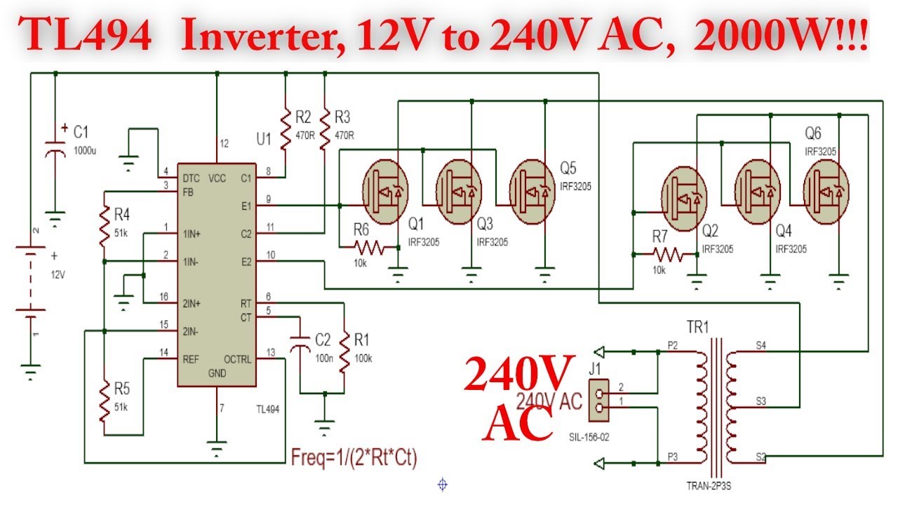
1.5v to 220v simple inverter circuit; On powering on the circuit using a 12v dc battery, a square wave signal is generated by the multivibrator circuit, but, in order to run an ac device without any issues, we require a pure ac sine wave signal from the inverter. 220v inverter circuit using irfz44 mosfet simple 100w with fet irf540 12v to 230vac rangkaian dc ke ac panduan 500w power circuits electrical4u 555 h bridge 4 n what is an diagram 7 you can high voltage easy 150 w full 100 watts working and for newcomers watt 500. This simple low power dc to ac inverter ( dc to ac converter) circuit converts 12v dc to 230v or 110v ac.
Circuit diagram for 12v to 220v inverter circuit.
Download a better high resolution circuit diagram here. Drain (d), source (s), gate (g), and substrate, which is called body (b) in our text. 220v inverter circuit using irfz44 mosfet simple 100w with fet irf540 12v to 230vac rangkaian dc ke ac panduan 500w power circuits electrical4u 555 h bridge 4 n what is an diagram 7 you can high voltage easy 150 w full 100 watts working and for newcomers watt 500. There are several ways to create an inverter when an engineer needs to convert dc to ac electricity.
Before jumping into the inverter circuit diagram, it is necessary to know the logical symbol of the power inverter.
This is the complete circuit diagram of a 1250va/24v mosfet inverter with battery charger. Simple 12v to 230vac inverter circuit. The oscillator stage, the driver stage and the full bridge mosfet output stage. The circuit diagram of mosfet inverter.
This voltage should be suitably derived from one of the batteries which are being incorporated for driving the inverter circuit.
Thus to obtain a positive voltage (+v) across the load, the transistors q 1 and q 2 are turned. Note each transistor has four terminals: The circuit may be basically divided into three stages, viz. The circuit is simple low cost and can be even assembled on a veroboard.
Pwm inverter circuit diagram using ic sg3524 and mosfet.
All you need is a good soldering skills , a little bit […] 500w high power inverter circuit diagram. Simplest inverter using hybrid mosfets and igbts with unipolar pwm to scientific diagram. The transfer characteristics of an ideal inverter is shown below.
Inverters are used to convert dc voltage to ac voltage.
As a result, the circuit may require a large number of components to enhance the voltage. By doing simple modification you can also convert 6v dc to 230v ac or 110v ac. 1000w power inverter circuit diagram: 100 watt inverter 12vdc to 220vac with mosfet.
How to make simple inverter circuit diagram within 5 minutes;
Simplest inverter using hybrid mosfets and igbts with unipolar pwm to scientific diagram. Heatsink is required for cooling the mosfets. The arrangement of the inverter consists of four transistor, (mosfet or igbt).to obtain an ac waveform at the output, the transistors are turned on and off in pairs of q 1, q 2 and q 3, q 4. This is achieved by chopping off the excess rms voltage of the astable square wave signal from the multivibrator circuit.
Here are a few related posts you may find helpful, too:
Looking at the shown circuit diagram, the idea can be.